EasyManua.ls Logo

Samsung AE090RXEDEG User Manual

Samsung AE090RXEDEG
136 pages
To Next Page IconTo Next Page
Page #1 background imageLoading...
Page #1 background image
ECO HEATING SYSTEM CONTENTS
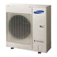
ECO HEATING SYSTEM
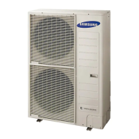
OUTDOOR UNIT
TANK INTEGRATED
HYDRO UNIT
1. Precautions
2. General Overview
3. Disassembly and Reassembly
4. Troubleshooting
5. PCB Diagram
6. Wiring Diagram
7. Reference Sheet
Model :
(Split)
AE040RXEDEG
AE060RXEDEG
AE090RXEDEG
AE090RXEDGG
(Mono)
AE050RXYDEG
AE080RXYDEG
AE120RXYDEG
AE160RXYDEG
AE080RXYDGG
AE120RXYDGG
AE160RXYDGG
(Split)
AE200RNWSEG
AE260RNWSEG
AE260RNWSGG
(Mono)
AE200RNWMEG
AE260RNWMEG
AE260RNWMGG
AE090RNYDEG
AE090RNYDGG
HYDRO UNIT

Other manuals for Samsung AE090RXEDEG

Questions and Answers:

Samsung AE090RXEDEG Specifications

General IconGeneral
BrandSamsung
ModelAE090RXEDEG
CategoryHeat Pump
LanguageEnglish

Summary

Precautions

1-1 Precautions for the Service

Guidelines for service personnel during equipment repair and assembly.

1-2 Precautions related to static electricity and PL

Safety measures for handling PCB and avoiding electrical interference.

1-3 Precautions for the Safety

Critical safety guidelines for electrical work and general product handling.

1-4 Precautions for handling refrigerants

Safety measures when working with refrigerant systems.

1-5 Precautions for brazing

Procedures and safety for brazing refrigerant lines.

1-6 Precautions for charging refrigerants

Guidelines for safely charging refrigerant into the system.

General Overview

2-1 Features of the System

Overview of key technological features of the EHS system.

2-1-1 Key Features of the EHS (Split)

Specific features and benefits of the EHS Split system.

Disassembly and Reassembly

3-1 Tank Integrated Hydro Unit / Hydro Unit

Step-by-step instructions for disassembling the hydro unit.

3-2 Outdoor Unit

Step-by-step instructions for disassembling the outdoor unit.

Hand Tool Sets

List of hand tools required for disassembly and reassembly procedures.

AE090RNYD※G Disassembly

Disassembly steps for the AE090RNYDGG model.

AE090RXED※ Disassembly

Disassembly steps for the AE090RXED model.

AE040RXEDS/AE060RXEDS Disassembly

Disassembly steps for AE040/060RXEDS models.

AE050RXYD※※ Disassembly

Disassembly steps for AE050RXYD models.

AE120/160RXYD※※ Disassembly

Disassembly steps for AE120/160RXYD models.

AE080RXYD※※ Disassembly

Disassembly steps for AE080RXYD models.

Troubleshooting

4-1 Wired remote controller

Troubleshooting common error codes displayed on the wired remote controller.

4-2-1 Communication Error After Finishing Tracking

Troubleshooting steps for communication errors after tracking.

Tank Integrated Hydro Unit / Hydro Unit Troubleshooting

4-3-1 EEPROM Error

Troubleshooting for EEPROM errors in Hydro Unit.

4-3-2 Water Pump & Flow Sensor Error

Troubleshooting for water pump and flow sensor errors.

4-3-3 Water Pump & Flow Sensor Error

Troubleshooting for water pump and flow sensor errors (normal flow rate).

4-3-4 Hydro Unit Temperature Sensor (Open/Short)

Troubleshooting for open/short circuit in Hydro unit temperature sensors.

4-3-5 Communication Error After Finishing Tracking (Hydro Unit)

Troubleshooting communication errors between Hydro and outdoor units.

Items to Check Before Diagnostics

4-4-1 Test Run Mode and View Mode

Guide to using test run and view modes for diagnostics.

Troubleshooting by Symptoms

4-5-1 Communication Error After Finishing Tracking (E202)

Troubleshooting communication errors after tracking (E202).

4-5-2 Time Out of Communication Error Between MAIN PBA and INV. PBA (E203)

Troubleshooting communication timeouts between MAIN and INV. PBA (E203).

4-5-3 Temperature Sensor Error (E221, E231, E251, E320)

Troubleshooting temperature sensor errors (E221, E231, E251, E320).

4-5-4 Fan Error (E458, E475)

Troubleshooting fan errors (E458, E475).

4-5-5 Compressor Error (E461, E467)

Troubleshooting compressor errors (E461, E467).

4-5-6 Current Trip Error (E462, E463)

Troubleshooting current trip errors (E462, E463).

4-5-7 IPM (IGBT Module) Over Current Error (E464)

Troubleshooting IPM over current errors (E464).

4-5-8 DC-Link Voltage Under/Over Error (E466)

Troubleshooting DC-link voltage errors (E466).

4-5-9 GAS Leak Error (E554)

Troubleshooting gas leak errors (E554).

4-5-10 Heating/Cooling Mode Anomalies

Troubleshooting heating/cooling mode anomalies.

4-5-11 Outdoor Unit Not Powered On – Initial Diagnosis

Initial diagnosis steps for outdoor unit power issues.

PCB Diagram

5-1 Tank Integrated Hydro Unit / Hydro Unit

PCB diagram for the Tank Integrated Hydro Unit.

5-2 Outdoor Unit (Main PCB)

PCB diagram for the Outdoor Unit (MAIN PCB).

Inverter PCB (AE090RX**EG)

Inverter PCB diagram for AE090RX**EG models.

Inverter PCB (AE120/160RX**EG)

Inverter PCB diagram for AE120/160RX**EG models.

Inverter PCB (AE080/090/120/160RX**GG)

Inverter PCB diagram for AE080/090/120/160RX**GG models.

EMI PCB (AE090/120/160RX**EG)

EMI PCB diagram for AE090/120/160RX**EG models.

EMI PCB (AE080/090/120/160RX**GG)

EMI PCB diagram for AE080/090/120/160RX**GG models.

Sub-Heater PCB (AE080/090/120/160RX****)

Sub-heater PCB diagram for AE080/090/120/160RX models.

Inverter PCB (AE040/050/060RX****)

Inverter PCB diagram for AE040/050/060RX models.

Main PCB (AE040/050/060RX****)

Main PCB diagram for AE040/050/060RX models.

Wiring Diagram

6-1 Tank Integrated Hydro Unit / Hydro Unit

Wiring diagram for Tank Integrated Hydro Units.

6-1-1 3Phase Model (AE***RNW*GG)

Wiring diagram for 3-phase Tank Integrated Hydro Units.

6-1-2 1Phase Model (AE***RNW*EG)

Wiring diagram for 1-phase Tank Integrated Hydro Units.

6-1-3 3Phase Model (AE090RNYDGG)

Wiring diagram for AE090RNYDGG 3-phase models.

6-1-4 1Phase Model (AE090RNYDEG)

Wiring diagram for AE090RNYDEG 1-phase models.

6-2 Outdoor Unit

Wiring diagram for Outdoor Units.

3Phase (AE080/090/120/160/RX**GG)

Wiring diagram for 3-phase outdoor units.

1Phase (AE090/120/160/RX**EG)

Wiring diagram for 1-phase outdoor units.

1Phase (AE040/050/060RX****)

Wiring diagram for 1-phase AE040/050/060RX models.

Reference Sheet

7-1 Index for Model Name

Guide to understanding model name structure and components.

7-2 Tank Integrated Hydro Unit (Split)

Component list and diagram for split tank hydro units.

7-3 Tank Integrated Hydro Unit (Mono)

Component list and diagram for mono tank hydro units.

7-4 Hydro Unit (Split)

Component list and diagram for split hydro units.

7-5 FSV Data Check and Update using S-NET Pro2

Procedure for checking and updating FSV data using S-NET Pro2.

7-6 EHS FSV Values Import and Export

Steps for importing and exporting FSV values for EHS units.

Related product manuals