Do you have a question about the Samsung AM036TXMDCH and is the answer not in the manual?
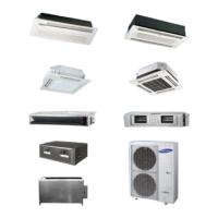
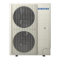
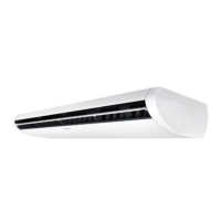
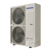
Details key features of the outdoor unit, including fan motors, heat exchangers, and compressors.
Provides detailed technical specifications for different models like performance, power, and dimensions.
Lists essential tools required for safely disassembling and reassembling the outdoor unit.
Explains how error codes are displayed on the unit and lists common error codes.
Guide to diagnose and resolve communication errors between indoor and outdoor units (E201).
Troubleshooting steps for MCU branch part setup issues and address errors (E211).
Procedures for diagnosing and fixing sensor and component errors like E221, E403.
Covers various other system faults including refrigerant leaks and voltage issues (E439, E466).
Illustrates the layout and component identification of the main PCB.
Shows the inverter PCB layout and connector functions.
Details the Electromagnetic Interference (EMI) PCB layout and connections.
Provides the wiring schematic for single-phase models.
Visual representation of the refrigerant flow within the system.
Explains the coding system used for model names and product features.
Instructions for performing operational checks and troubleshooting 'Undetermined' results.
Details the process and interpretation of automatic refrigerant amount detection.
| Brand | Samsung |
|---|---|
| Model | AM036TXMDCH |
| Category | Air Conditioner |
| Language | English |