Do you have a question about the Samsung AQV36JANKCV and is the answer not in the manual?
Safety guidelines for professional installation of the air conditioner.
Electrical safety precautions for power supply and circuit breaker usage.
Safety measures to follow during the air conditioner's operation.
Procedures for safely disposing of the air conditioner and its components.
General safety precautions and handling advice for the unit.
Highlights key features: energy saving, cleaning system, and remote control.
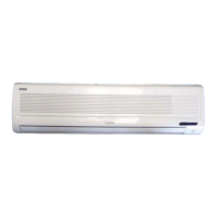
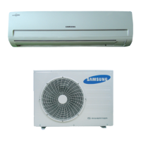
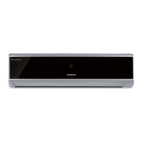
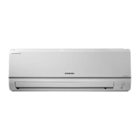
Identification of indoor and outdoor unit components.
Detailed technical specifications for cooling, heating, power, and dimensions.
Comparison between AQV36JA and AQ36WB models.
List of included accessories and their part numbers.
Step-by-step guide to disassembling the indoor unit's parts.
Procedures for disassembling the outdoor unit's components.
Lists indoor unit error codes and LED indicators.
Details outdoor unit error codes and their explanations.
Systematic troubleshooting for various symptoms and errors.
Guidelines for inspecting printed circuit boards.
Methods for inspecting key physical components.
Guide to setting unit options via remote control.
Exploded diagram and parts list for the indoor unit.
Exploded diagram and parts list for the outdoor unit.
Components list for the indoor control assembly.
Indoor main PCB layout and connector pinouts.
Component list for the main PCB.
Components list for the outdoor control assembly.
Outdoor inverter PCB layout and pinouts.
Outdoor main PCB layout and pinouts.
Outdoor EMI PCB layout and connections.
Outdoor display PCB layout and details.
Component list for outdoor inverter PCB.
Component list for outdoor main PCB.
Component list for outdoor EMI PCB.
Component list for outdoor display PCB.
Diagram showing electrical connections between units and components.
Schematic of the indoor unit's main PCB modules.
Schematic diagram for the display PCB.
Overview of outdoor unit PCB modules.
Schematic breakdown of the inverter PCB.
Schematic diagram of the EMI PCB.
Visual representation of refrigerant flow.
Explanation of basic operation modes and functions.
Identifies remote control buttons and indicators.
Instructions for cleaning the unit and filters.
Diagrams and procedures for unit installation.
Graph showing pressure vs. temperature.
Table of pressure and capacity marks.
Guide to model code structure and designations.
| Brand | Samsung |
|---|---|
| Model | AQV36JANKCV |
| Category | Air Conditioner |
| Language | English |