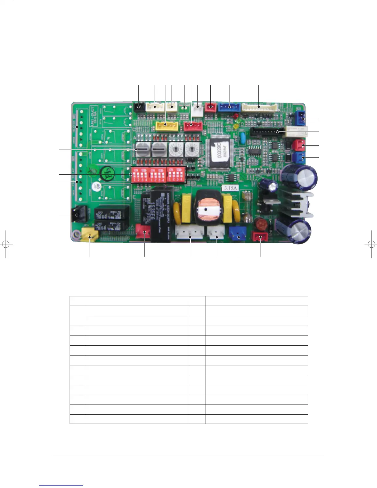
PCB Diagram
9-10Samsung Electronics
!
Float Switch : SMW250-02(BLK)
@
Room Temperature : SMW250-04(WHT)
EVA in Temperature : SMW250-04(WHT)
#
EVA out Temperature : SMW250-02(WHT)
$
Heater Temperature : SMW250-02(YEL)
%
Wired Remote Controller Power(12V) : YW396-02(WHT)
^
Control Signal : SMW250-02(RED)
&
EEV : SMW250-05(BLU)
*
Display : SMW200-11(WHT)
(
Operating Check Signal : SMW250-04(RED)
)
HALL IC : SMW250-03(BLU)
1
Download : SMW200-10(WHT)
2
COM 1 : YW396-02(RED)
3
COM 2 : YW396-02(BLU)
4
Load Control Signal : SMW250-05(YEL)
5
Heater : YW396-07AV(WHT)
6
Address Switch
7
Option Switch
8
Fan (Tap Control) : YW396-09AV(WHT)
9
Ventilator : YW396-03AV(BLK)
0
Drain Pump : YW396-03AV(YEL)
“
Hot Coil : YW396-03AV(RED)
‘
Fan (SSR) : YW396-05AV(WHT)
+
Trans in : YW396-03AV(WHT)
=
Main Power : YW396-03AV(BLU)
Q
Trans out : YW250-03(RED)
)
1
2
3
5
8
9
7
“ Q=+‘0
! @ 4 (# $ % ^ & *
6
24103A(1)_2 12/23/05 12:57 PM Page 6-45



 To Next Page