51
Ⅳ.ADJUSTMENT
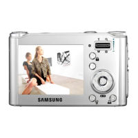
STROBO TEST
TEST COUNT : 10
LUMINANCE : 627
FLASH ADJ IN WIDE
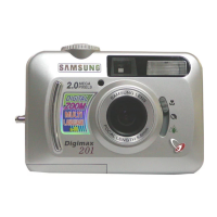
STROBO TEST
TEST COUNT : 3
LUMINANCE : 3768
FAIL!!
FLASH ADJ IN WIDE
< Figure 6-2 >
< Figure 6-1 >
6) FLASH ADJUSTMENT
After changing the MAIN PCB and SUB PCB, adjust the FLASH.
< Codes of program >
< How to adjust the item >
a. Arrange a 36% reflect chart in a darkroom.
b. Arrange a camera in a darkroom.
c. The distance between the reflect chart and the camera should be 80cm.
d. Insert the codes and save the program in the SD card.
e. Insert the SD card to the camera and turn on the camera.
f. After completing the adjustment, the camera will be turned off.
※ If the adjustment is incomplete, <Figure 6-2> will display with beep sound. In this case, re-try the adjustment
process.
BASIC PROGRAM FLASH ADJUSTMENT
<1> PROCESS CODE ; <1>13;
<2> 65535 ; <2>65535;
<3> PROCESS CODE ; <3>13,1;
<4> 0 OR 1 ; <4>1;
<5> 0 OR 1 ; <5>1;
<6> CONDITION ; <6>1300,100,620,500,345,245,10;
<7> SPEC ; <7>;
<8> NOT <8>;
<9> NOT <9>;
<10> NOT <10>;
<11> NOT <11>;
<12> NOT <12>;
<13> NOT <13>;
<14> 0 <14>65535;
<15> 0 <15>0;
 Loading...