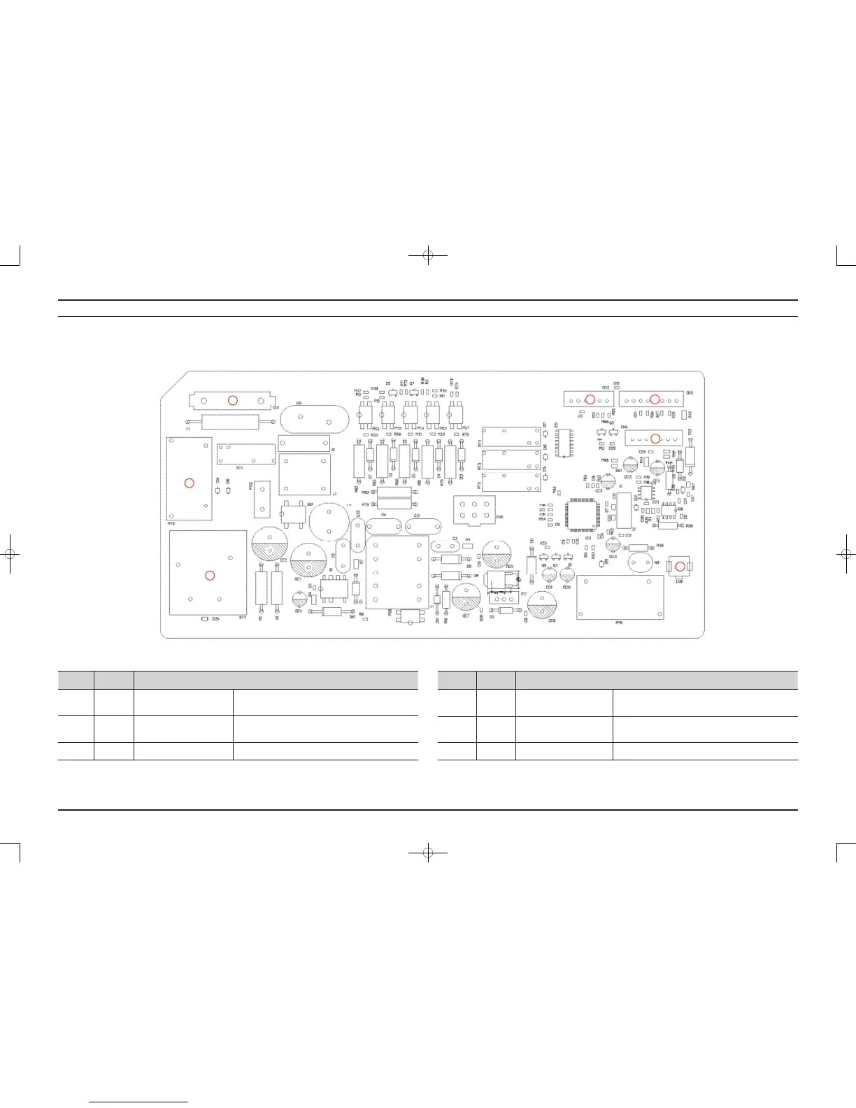
5. PBA DIAGRAM
5-1. MAIN PBA
► ThisDocumentcannotbeusedwithoutSamsung’sauthorization.
Location Part No. Function
1 CN1
ACCONNECTION
CONNECTOR
SuppliesACpowertothePBA
2 CN2
SUBPBACOMMUNICATION
CONNECTOR
TheconnectorthatcontrolscommunicationswiththeSubPBA
correspondingtotheDisplay.
3 CN3 MICOMFLASHCONNECTOR TheconnectorthatwritessoftwareontotheMICOM.
Location Part No. Function
4 CN4
SENSORCONNECTION
CONNECTOR
Connectsthetemperaturesensorinordertodetectthe
temperatureoftheheater.
5 CN6
SETGROUNDCONNECTION
CONNECTOR
TheconnectorconnectingtheDryerSetandthegroundofthe
PBA
6 RY7 HEATER1OPERATIONRELAY TherelaythatturnstheHeater1onandoff.
1
2 3
4
7
5
6
复件 Hudson_Dryer_SM_E.indb 38 2012-4-2 15:20:58
 Loading...