EasyManua.ls Logo

Samsung DVM S AM260HXVAGH User Manual

Samsung DVM S AM260HXVAGH
112 pages
To Next Page IconTo Next Page
Page #1 background imageLoading...
Page #1 background image
DVM S
AM✴✴✴FXVAGR Series
AM✴✴✴FXVAGH Series
AM✴✴✴HXVAGH Series
AM✴✴✴MXVNR Series
Air Conditioner
installation manual
imagine the possibilities
Thank you for purchasing this Samsung product.
DB68-03850A-14

Table of Contents

Question and Answer IconNeed help?

Do you have a question about the Samsung DVM S AM260HXVAGH and is the answer not in the manual?

Samsung DVM S AM260HXVAGH Specifications

General IconGeneral
ModelAM260HXVAGH
TypeDVM S
Cooling Capacity26.0 kW
Power Source380-415V, 3Ph, 50Hz
RefrigerantR410A
Operating Temperature (Heating)-20 to 24°C

Summary

Safety Precautions

General Safety Information

Key safety guidelines for installers and users.

Warning and Caution Signs

Explains the meaning of warning and caution signs.

Preparing for installation

Selecting installation location

Base construction and installation of the outdoor unit

Refrigerant pipe installation

Refrigerant pipe work guidelines

General guidelines and tools for refrigerant pipe installation.

Selecting refrigerant pipe

Pipe size to outdoor unit (A)

Pipe size between branch joints (B)

Branch joint types (C, D, E)

Branch Joint between Outdoor Units (C)

Details on branch joints connecting outdoor units.

First Branch Joint (D)

Guidance on selecting first branch joints.

Branch Joint (E)

Guidance on selecting branch joints.

Pipe size to outdoor unit (A) for HR

Pipe size between branch joints (B) for HR

Branch joint types (C, D, E) for HR

Additional refrigerant calculation

Additional refrigerant per indoor unit

Total additional refrigerant calculation method

Refrigerant pipe installation safety

Pipe Welding Safety and Nitrogen Flushing

Safety and procedure for pipe welding with nitrogen flushing.

Cutting and Flaring Pipes

Connecting Flared Pipes

Connecting Refrigerant Pipe to Outdoor Unit

Welding Pipe to Outdoor Unit Cautions

Safety precautions during pipe welding near the unit.

Allowable Refrigerant Pipe Lengths (H/P)

Allowable Refrigerant Pipe Lengths (H/P) Continued

Allowable Refrigerant Pipe Lengths (H/R)

Allowable Height Difference and Lengths (H/R)

Maximum Allowable Height Difference

Limits on height differences between units.

Allowable Refrigerant Pipe Lengths (H/R) Continued

Installing Branch Joints

Installing Distribution Header

MCU Installation and Specifications

Installing Indoor Units with MCU

Connecting Pipes to MCU and Outdoor Units

Electrical Wiring Work

Circuit Breaker and Power Cable Specs

Specifies circuit breaker and power cable requirements.

Electrical Wiring Work Continued

Circuit Breaker and Power Cable Specs (Continued)

Continues specification of circuit breakers and power cables.

Electrical Wiring Work Cautions

Power and Communication Cable Configuration

Power Wiring Diagram (3 Phase)

Connecting Power Terminal

Connecting MCUs (Examples 1 & 2)

Connecting MCUs (Example)

Grounding Work Guidelines

Grounding the Power Cable

Table for grounding power cables based on installation place.

Air Tightness Test and Vacuum Drying

Air Tightness Test Procedure

Steps for performing air tightness tests using nitrogen gas.

Vacuum Drying Pipes and Indoor Units

Pipe Insulation Requirements

Insulating the Refrigerant Pipe

Refrigerant Charging (Turkey Market Only)

Refrigerant Regulations and Information

Regulations and safety info for refrigerants.

Refrigerant Charging (Turkey Market Only) - Single Installation

Refrigerant Charging (Turkey Market Only) - Module Installation and Service Valves

Module Installation Charging

Procedure for charging refrigerant in module installations.

Using Service Valves for Gas

Details on using service valves for gas charging.

Setting Outdoor Unit Options and Key Functions

Option Switches and Settings (Type A)

Details option switches and settings for Type A units.

Outdoor Unit Option Switches (Type B)

Setting Outdoor Install Options

Step-by-step guide for setting installation options.

Setting Options with Tact Switches

Key Operations and View Mode Checking

K1 Key Operations

How to use K1 key for operations and view mode checks.

K2 Key Operations

K4 Key Operations (Part 1)

K4 Key Operations (Part 2)

MCU and Pipe Address Settings (HR Only)

Setting MCU Address and Ports

How to set MCU addresses and ports.

Manual Pipe Address Setting

Automatic Pipe Address Setting (Auto Pairing)

Auto Pipe Pairing Operation Steps

Post-Installation Checks

Electrical Resistance and Voltage Checks

Insulation resistance and voltage/phase checks before power.

Final Installation Verification

Refrigerant Pipe Work Checks

Checks for refrigerant pipe installation correctness.

Electrical Wiring Work Checks

Checks for electrical wiring and grounding.

Inspection and Test Operation

Precautions Before Test Operation

Safety precautions before starting test operations.

Checklist Before Auto Trial Operation

Checklist of items to verify before auto trial operation.

Auto Trial Operation Procedure

E503 Error Troubleshooting

E505, E506 Error Troubleshooting

Automatic Refrigerant Amount Detection Function

Detection Procedure and Results

Steps for detecting refrigerant amount and interpreting results.
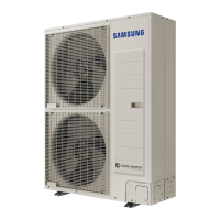
Actions for Refrigerant Detection Results

Related product manuals