Do you have a question about the Samsung HLT6187SX and is the answer not in the manual?
Provides essential safety guidelines for handling the TV and its components during operation and installation.
Details specific safety measures for service personnel to follow during repair procedures.
Explains measures to prevent damage to sensitive components from static electricity.
Outlines safety procedures for correctly installing the TV unit to ensure proper ventilation and safety.
Describes the detailed features, specifications, and key ICs used in the TV's hardware.
Summarizes the main hardware configuration, software features, picture, sound, and terminals.
Compares technical specifications across different TV models for analytical purposes.
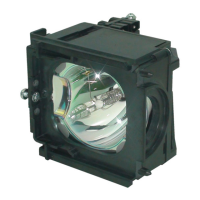
Lists all supplied accessories and optional items that can be purchased for the TV.
Provides instructions for checking key items after component replacement for service.
Details the procedure to enter the TV's special service mode using the remote control.
Lists factory data settings, their ranges, and default values for service adjustments.
Explains procedures for adjusting vertical/horizontal position and CCA color correction.
Guides on how to perform software upgrades via the USB port for firmware updates.
Covers screen tilt, focus alignment, and illumination adjustment procedures.
Provides an exploded view and detailed part list for the HLT6187SX/XAA model.
Lists specific electrical parts, their codes, and specifications for service purposes.
Identifies common error modes, such as noise and black screens, and initial checks.
Details troubleshooting steps based on LED indicators and protect status.
Presents a high-level overview of the TV's main functional blocks and signal flow.
Provides detailed block diagrams for the SMPS and LED driver boards.
Illustrates the overall internal wiring and connections between major TV components.
Shows the physical layout of components and connectors on the main board.
Diagram of the power board, showing key components and connections.
Diagram of the sub-power board and its primary power supply connections.
Diagram of the main board detailing its functions and connectors.
Diagram of the jack board illustrating input/output terminals.
Diagram of the DMD board, its key parts, and their functions.
Diagram of the LED driver board and the roles of its connectors.
Detailed electrical schematics for the main board components and circuits.
Electrical schematics for the TV's input/output jack board.
Schematic diagrams illustrating the DMD board's circuitry and connections.
Schematic diagram detailing the TV's power supply circuit.
Explains operation of the TV's front panel controls, indicator lights, and remote sensor.
Describes new features like RS-232C communication and its settings.
Provides step-by-step instructions and photos for disassembling the TV's main components.
Describes the overall functional blocks and signal flow of the DLP TV system.
Details the function and operation of the power supply and digital boards.
Explains output voltage states and terminal characteristics of the DMD board.
Discusses issues related to cable length and digital broadcast reception.
Provides definitions for technical terms used throughout the manual.
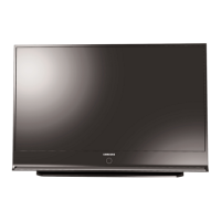
| Screen Size | 61 inches |
|---|---|
| Display Technology | DLP |
| Resolution | 1920 x 1080 |
| Aspect Ratio | 16:9 |
| HDMI Ports | 3 |
| Component Video Inputs | 2 |
| S-Video Inputs | 1 |
| Display Type | Rear Projection |
| Contrast Ratio | 10000:1 |
| Inputs | HDMI, Component, Composite, S-Video |
| Speakers | 10W x 2 |