Do you have a question about the Samsung LN26R71BAX and is the answer not in the manual?
General safety guidelines to prevent hazards like electrical shock.
Precautions to follow before and during service procedures.
Techniques to prevent ESD damage to components.
Precautions to take during the installation process.
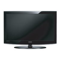
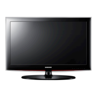
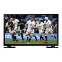
Describes design aspects and aesthetic features of the TV.
Detailed technical specifications for the LN23R71BAX/WAX models.
Detailed technical specifications for the LN26R71BAX model.
Detailed technical specifications for the LN32R71BAX model.
Detailed technical specifications for the LN40R71BAX model.
Comparison of key specifications across different TV models.
Specifications related to optional accessories and features.
General guidelines for performing TV alignments and adjustments.
Step-by-step instructions to enter the TV's service mode.
Information on factory settings, calibration, and option bytes.
Procedures for adjusting TV picture quality and white balance.
Instructions for updating the TV's firmware via RS-232C or UART.
Initial checks and common troubleshooting steps for TV issues.
Detailed diagnostic checkpoints for specific error modes like No Power, No Video.
Visual diagram showing the assembly of parts for specific models.
List of part numbers and specifications for the LN23R71BAX model.
List of part numbers and specifications for the LN23R71WAX model.
Visual diagram showing the assembly of parts for specific models.
List of part numbers and specifications for the LN26R71BAX model.
Visual diagram showing the assembly of parts for specific models.
List of part numbers and specifications for the LN32R71BAX model.
Visual diagram showing the assembly of parts for specific models.
List of part numbers and specifications for the LN40R71BAX model.
Detailed list of electrical components with codes and specifications.
Detailed list of electrical components with codes and specifications.
Detailed list of electrical components with codes and specifications.
Detailed list of electrical components with codes and specifications.
High-level diagram illustrating the TV's functional blocks.
Overall wiring diagram of the TV's internal connections.
Diagram showing the physical arrangement of components on the main board.
Details on the characteristics and functions of connector pins.
Diagram showing the physical arrangement of components on the power board.
Schematic for power and sound circuits.
Schematic for input/output jacks.
Schematic for the microcontroller unit.
Schematics for specific options and power-related circuits.
Schematic illustrating typical circuit applications.
Description of the TV's front panel, buttons, and indicators.
Detailed explanation of the TV's input and output connection ports.
Comprehensive guide to the functions of the remote control.
Instructions for attaching the TV stand.
Instructions for mounting the TV using a wall mount kit.
Step-by-step guide for disassembling the TV.
Step-by-step guide for reassembling the TV.
Visual layout of the main printed circuit board.
Diagram of the power supply board for 23-inch models.
Diagram of the power supply board for 26" and 32" models.
Diagram of the power supply board for 40-inch models.
High-level block diagram of the TV's main functional blocks.
Detailed block diagram of the TV's main internal circuits.
Description of the SMPS (Switch Mode Power Supply) board.
Definitions of technical terms used in the manual.
Pin assignments for various connectors like DVI-D, Component, S-Video, etc.
Timing specifications for LCD panel signals in Mode1.
Details on various LCD panel models and their specifications.