7
ENGLISH
3. Ƹϑʪϩиͱͱθͱθʪϑʀθʪиϑϩͱѣуϩ˵ʪɵɇʀʀͱЭʪθϩͱϩ˵ʪиɇࢋAͱʪʀϩϩ˵ʪΧͱиʪθʀɇɵʪϑ࣍ǤߢࡡǤߣ࣎ɇʒ
communication cables (F1, F2) to the terminals on the back of the front cover while adjusting to a suitable
length.
4. Ǯ˵ʪʀͱʪʀϩ˝ϩ˵ʪΧͱиʪθʀɇɵʪϑϩͱǤߢɇʒǤߣࡡ˙ɇϑϩʪϩ˵ʪťA9ϩʪθɇϑʀθʪиϑ࣍AĘߦ࣎ϩͱɇϩͱθαЇʪͱ˙
6 N·cm or less.
Ɗʀθʪиϑіʪࡠđߤуߧ
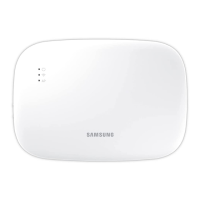
• You can connect up to 16 indoor units to a Wi-Fi Kit.
ߣ Ǥߣ Ǥߤߤ ߥ ߦ
Ķ
Ĺĺ
ⓐ
ĸ
ķ
10 and
over
10 and over
50 and over
10 and over
Screw
holes
࢘
Be sure to secure space of at least
10 mm (up/right/left) and 50 mm
(down) around the back cover
ɵʪ˙ͱθʪѣу˝ϩ˵ʪɵɇʀʀͱЭʪθͱ
the wall.
࢘
Fix the screws to the
screw holes.
࢘
Do not over-tighten the PCB
terminal.
ǤߢǤߣߢߣ
Wi-Fi Kit
PCB port
Indoor unit
Unit: mm
Back cover
Item Contents Item Contents
ĵ
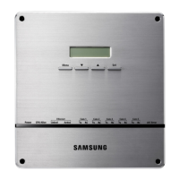
Power/communication terminals
ĸ
LED
Ķ
Tracking/Reset button
Ĺ
Network PBA
ķ
Micro SD card slot
ĺ
Interface module PBA
5. Assemble the Wi-Fi Kit again.
• Ãϑʪθϩϩ˵ʪ˙θͱϩʀͱЭʪθϩͱϩ˵ʪЇΧΧʪθ˝θͱͱЭʪϑɇϑϑ˵ͱиϩ˵ʪѣ˝Їθʪࢋ˙ϩʪθɇϑϑʪɵцࡡ
make sure that there is no gap between the covers.
NOTE
NOTE
ki]_TW_[Y]hTW[piptuhzhGvjmG~TmGrl|luUGGG^ YWYYTXXTYZGGG㝘㤸GXXaWWaZZ
 Loading...