Do you have a question about the Samsung MultiXpress K4 Series and is the answer not in the manual?
General safety instructions for servicing, part usage, and laser safety.
Specific precautions for handling toxic materials and electrical/fire hazards.
Guidelines for personal safety and product handling to avoid injury and damage.
Techniques to reduce component damage caused by static electricity.
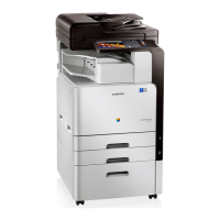
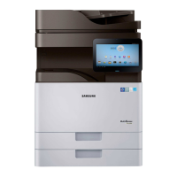
Overview of key product features including printing speed, processor, memory, document feeder, and LCD.
Detailed specifications for the machine like processor, memory, storage, interface, power, and warmup time.
Comprehensive table of general machine specifications like CPU, memory, storage, interface, and power.
Specifications for printing speed, FPOT, resolution, printer languages, font, and OS support.
Specifications for scanning capabilities including speed, color modes, file formats, resolution, and destinations.
Specifications for copying functions like speed, FCOT, resolution, reduce/enlarge, and features.
Specifications for fax functionality including communication system, speed, memory, and features.
Details on paper input capacity, media sizes, types, weight, and sensing for trays.
Specifications for application software, mobile printing, and security solutions.
Information on toner cartridges, OPC drum unit, and waste toner container yield.
List of maintenance parts with part codes, life expectancy, and remarks.
List of optional accessories available for the machine, including their models.
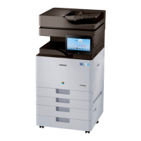
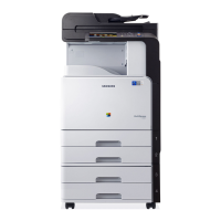
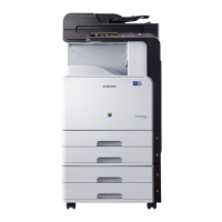
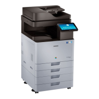
Diagrams showing the external view of the machine with numbered parts.
Overview of the paper feeding system, including its main components.
Description of the paper feeding system's function and main components.
Detailed explanation of rollers and their functions within the feeding system.
Explanation of the image creation process, including drum charging, laser exposure, development, and transfer.
Overview of the printing process stages from OPC drum charge to cleaning.
Overview of the imaging unit, including drum diameter and developing gap.
Description of the image fusing process and the fuser unit's components.
Overview of the fuser unit, explaining its heat and pressure application for fusing toner.
Overview of the LSU, its components, and optical path.
Detailed explanation of the LSU's components and function in forming a latent image.
Overview of the machine's drive system, including motors and their functions.
Table listing drive motors, their types, quantity, and functions.
Overview of the scanner system, its parts, and functions.
Explanation of the scanner's role, modules, and carriage movement.
Diagram and description of the scanner system's construction and components.
Overview of the DSDF, including its parts and functions.
Description of DSDF components like stacker assembly, rollers, and CIS module.
Overview of the RADF, its parts, and functions.
Description of RADF components like registration rollers and document trays.
Overview of the machine's electrical circuit system components.
Details about the main controller's processor, memory, and connectivity.
Specifications and connections for the SMPS board supplying power.
Specifications and connections for the High Voltage Power Supply (HVPS) board.
Essential precautions before assembling, disassembling, and handling PBAs.
Guidelines for using approved parts, noting screw locations, and checking power cords.
Precautions for handling Printed Circuit Board Assemblies (PBAs) to prevent static damage.
Procedures for machine cleaning and maintenance tasks.
Steps for cleaning the scan glass and DSDF white bar.
Procedures for replacing key maintenance parts like the drum unit.
Step-by-step guide for removing and replacing the drum unit.
Detailed steps for removing and replacing the developer unit.
Procedure for removing and replacing the fuser unit.
Procedures for replacing major service parts of the machine.
Steps for removing the left cover of the machine.
Procedure for removing the rear cover of the machine.
Steps for removing the Laser Scanning Unit (LSU).
Steps for removing the High Voltage Power Supply (HVPS) board.
Procedure for removing the Operator Panel Electronics (OPE) Unit.
Steps for removing and replacing the main board.
Procedure for removing the developer fan.
Steps for removing the SMPS board.
Procedure for removing the Fuser Drive Board (FDB).
Steps for removing the Fuser/Exit Drive Unit.
Procedure for removing the main drive unit.
Steps for removing the pick-up drive unit.
Procedure for removing the toner duct drive unit.
Steps for removing the toner supply drive unit.
Procedure for removing the toner duct.
Steps for removing the waste toner container sensor.
Procedure for removing the auto size sensor.
Steps for removing the exit unit.
Procedure for removing the side unit and its stoppers.
Steps for removing the fuser out sensor.
Procedure for removing the temperature and duplex sensors.
Steps for removing the Multi-Purpose (MP) unit.
Procedure for removing the pick-up unit and its sensors.
Procedure for removing the Dual Scan Document Feeder (DSDF) unit.
Steps for removing the DSDF board.
Procedure for removing the Reverse Automatic Document Feeder (RADF) unit.
Steps for removing the RADF board.
Steps for removing the scanner unit (platen unit).
Procedure for removing the scan glass.
Steps for removing the LED lamp module.
Procedure for removing the scanner imaging unit.
Steps for removing the scan joint board.
Procedure for removing the APS sensor.
Steps for removing the side cover open switch.
Procedure for removing the front cover open switch.
Steps for removing and installing the Hard Disk Drive (HDD).
Procedures for installing the Card Reader or NFC Kit.
Detailed steps for installing the Card Reader or NFC Kit on the working table.
Procedures for installing the Card Reader or NFC Kit inside the cover-scan front.
Steps for installing the working table.
Procedures for replacing DCF unit components.
Steps for removing the DCF main board.
Procedure for removing the DCF feed motor.
Steps for removing the DCF pick-up motor.
Procedures for disassembling and reassembling the finisher.
Steps for removing the finisher entrance sensor.
Procedure for removing the finisher entrance motor.
Steps for removing the finisher exit sensor.
Procedure for removing the finisher exit motor.
Steps for removing the sub paddle shaft sub assembly.
Procedure for removing the front jogger motor.
Steps for removing the front jogger home sensor.
Procedure for removing the rear jogger motor.
Steps for removing the rear jogger home sensor.
Procedure for removing the stapler unit.
Steps for removing the traverse home sensor.
Procedure for removing the traverse motor.
Steps for removing the stacker motor.
Procedure for removing the stacker encoder sensor.
Steps for removing the stacker lower limit switch.
Procedure for removing the stack beam sensor.
Steps for removing the stack position sensor.
Procedure for removing the paper holding lever solenoid.
Steps for removing the paper support motor.
Procedure for removing the paper support home sensor.
Steps for removing the ejector motor assembly.
Procedure for removing the main paddle motor.
Steps for removing the main paddle home sensor.
Procedure for removing the main paddle units.
Steps for removing the ejector assembly.
Procedure for removing the punch dust full sensor.
Steps for removing the door switch.
Procedure for removing the top door switch.
Overview of the control panel display, buttons, and power status indicators.
Explanation of display screen terms, menu navigation, and screen gestures.
Defines terms like Tap, Touch and Hold, Swipe, and Panning for screen interaction.
Description of the main home screen, navigation, and application menus.
Steps for creating and deleting shortcuts, and adding widgets.
Information on the notification bar and accessing additional panel functions.
Explanation of the status LED colors and their meanings for machine status.
Instructions for updating printer firmware via control panel or network.
Step-by-step guide for updating firmware using the printer control panel.
Procedure for updating firmware using the network via SyncThru Web Service.
Procedures for removing paper jams from various locations in the machine.
Instructions for clearing paper jams within the ADF.
Steps for clearing paper jams from trays, inside the machine, and the exit area.
Guide on how to enter the machine's service mode.
Step-by-step instructions for accessing the service mode.
Overview of the service mode menu structure.
Procedures for performing diagnostic tests on engine, fax, and scanner systems.
Details on engine NVM initialization and read/write operations for configuration.
Procedures for fax NVM read/write and test routines.
Procedures for scanner shading tests and NVM read/write operations.
Procedures for print adjustment, image position, and scan area adjustments.
Various service functions including memory clear, hard disk maintenance, network settings.
Procedure to reset the machine's main memory to factory default settings.
Functions for clearing device configuration, temporary data, and user data.
Function to enable/disable remote connections via Telnet, OSGI, and SMB protocols.
Function to set the system log message level for troubleshooting.
Procedure to copy system logs to USB memory for analysis.
Procedures for entering system recovery mode and performing HDD repair or format.
Function to adjust transfer values for optimizing image quality based on paper type.
Guide to understanding and resolving error codes displayed on the control panel.
Troubleshooting steps for paper mismatch errors in various trays.
Troubleshooting steps for various motor errors, focusing on Regi/MP and Fuser motors.
Troubleshooting steps for various fan errors, including duplex, deve, and OPC fans.
Troubleshooting steps for sensor errors, including fuser thermistors and inner temperature sensors.
Troubleshooting steps for toner cartridge errors like low toner, end of life, and compatibility.
Troubleshooting steps for drum unit errors, including replacement and cleaning.
Troubleshooting steps for fuser unit errors, including replacement and installation checks.
Troubleshooting steps for waste toner container errors like full or not installed.
Troubleshooting steps for developer unit errors, including end of life and supply issues.
Troubleshooting steps for transfer roller errors, including replacement.
Troubleshooting for errors related to optional trays, such as paper jams and low paper.
Troubleshooting steps for various inner finisher errors.
Troubleshooting steps for various paper jam errors in different trays and locations.
Troubleshooting steps for system-related errors like video system, HDD, MSOK, network, and UI issues.
Troubleshooting steps for fuser unit errors, including thermistor and halogen lamp issues.
Troubleshooting steps for LSU motor and installation errors.
Troubleshooting steps for DSDF errors like paper jams and sensor issues.
General guide to troubleshooting image quality issues.
Troubleshooting steps for vertical black lines in print output.
Troubleshooting steps for vertical light or white lines in print output.
Troubleshooting steps for horizontal periodic black lines and dots.
Troubleshooting steps for horizontal periodic light/dark lines and dots.
Troubleshooting steps for blurred images, often related to humidity or voltage.
Troubleshooting steps for foggy images, related to OPC voltage or toner supply.
Troubleshooting steps for light images, often related to transfer voltage or TC sensor.
Troubleshooting steps for uneven pitch and jitter in images, related to drive gears or LSU.
Troubleshooting steps for skewed images, related to cassette installation or rollers.
Troubleshooting steps for poor fusing performance, related to paper type, fuser unit, or temperature control.
Troubleshooting steps for stains on the back side of the paper.
Solutions for other miscellaneous problems.
Troubleshooting for image problems, specifically toner cartridge detection and paper edge contamination.
Troubleshooting for acoustic noise issues related to the fuser unit.
Troubleshooting for common scanner and document feeder issues.
Troubleshooting for drive unit problems, specifically noise during printing.
Troubleshooting for feeding system issues like cassette locking and paper pickup.
Troubleshooting for LSU motor noise issues.
Troubleshooting steps for software-related issues like driver installation and scan login failures.
Troubleshooting for electrical circuit issues like side cover recognition, SMPS voltage, HDD noise, networking, UI, and NFC.
Procedure for adjusting the ADF skew by modifying hinge position.
Overview of the SPDS application for service engineers.
Steps for installing and logging into the SPDS application.
Detailed guide for installing the SPDS app from the Google Play Store.
Procedure for user registration and inputting required information.
Steps for changing or resetting the user password.
Procedure for logging into the SPDS application.
Guide for selecting connection methods like WIFI-Direct and NFC.
Steps for confirming user information and customer consent.
Introduction to the SPDS menu, including Error Mode, Action Guide, etc.
Explanation of the Device Error Inquiry and detailed error information within SPDS.
Guide to using the Diagnosis Mode for checking device status.
Procedures for using the Test Mode to print various test patterns.
Explanation of the Information Mode for viewing configuration, supplies, and network details.
Procedures for cloning, admin login, export/import, and device reboot in service mode.
Procedure for uploading corrective actions and detailed information.
Handling exceptions related to device and server interface connections.
Diagram showing the electrical connections for the fuser and exit units.
Diagram illustrating the electrical connections for the pick-up drive side unit.
Diagram showing the electrical connections between the LSU and HVPS boards.
Diagram illustrating the electrical connections for the toner system components.
Diagram showing the electrical connections between the FDB and SMPS boards.
Diagram illustrating the UI connections to USB hubs and the main PBA.
Diagram showing connections for the front OPC unit, including sensors and motors.
Diagram of the scanner unit connections to the main PBA and DSDF CIS.
Diagram showing the DCF connections to the main PBA and finisher.
Diagram illustrating connections for Fax, Dual Network, and FDI modules.
List of recommended tools for troubleshooting and their uses.
Definitions of technical terms used in the manual.
Explanation of the model naming structure and function codes.
List of document revisions, dates, pages, and descriptions of changes.
| Category | Copier |
|---|---|
| Print Resolution | Up to 1200 x 1200 dpi |
| Duplex Printing | Yes |
| Scan Resolution (Optical) | Up to 600 x 600 dpi |
| Functions | Print, Copy, Scan, Fax |
| Print Speed (Black) | 40 ppm |
| Hard Disk Drive | 320 GB |
| Media Sizes Supported | A4, A5, B5, Executive, Custom |
| Media Types Supported | Plain Paper, Thick Paper, Thin Paper, Bond Paper, Cardstock, Recycled Paper, Archive Paper |
| Scan Destinations | Email, USB, Network, PC, FTP, SMB |
| Copy Speed (Black) | 40 cpm |
| Zoom Range | 25% - 400% |
| Interface | USB 2.0, Ethernet |
| Mobile Printing Support | Yes |
| Connectivity | USB, Ethernet, Wi-Fi |
| Operating System Compatibility | Windows, Mac, Linux |