96
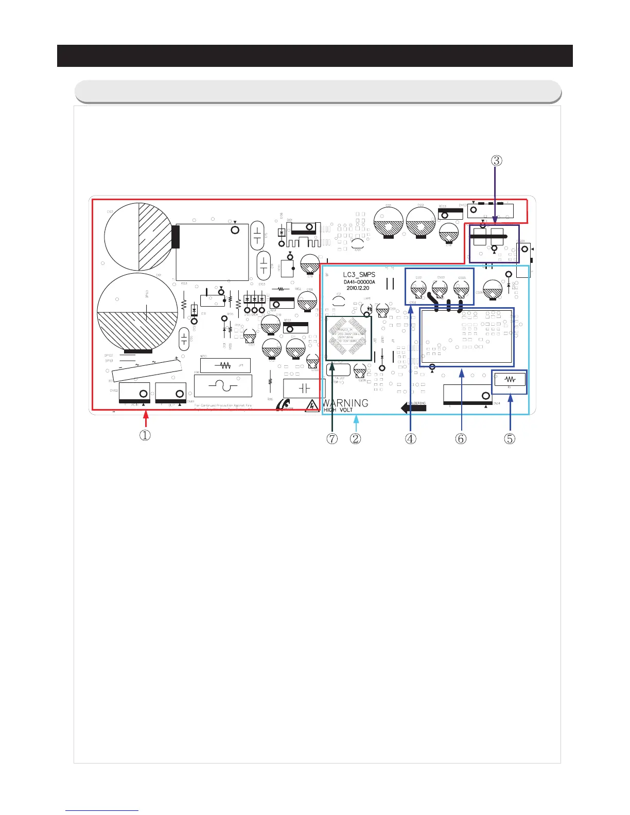
1. PCB Power Supply : From the SMPS circuit, it supplies 13.7V and 5V for the Main PBA control and
supplies 15V and 5V to the Inverter circuit for the Compressor control.
2. Inverter Control Circuit : Fridge Compressor Control Circuit.
3. COMP Driving / Feedback Circuit
It receives the COMP operation signals from the Main PBA and feedbacks the inverter errors to the
Main PBA.
4. BOOTSTRAP Charger : It is an independent power circuit for the driving of the IMP High-Phase IGBT.
5. Current Pickup Circuit : It pickups the currents taken by the Shunt resistance and does the PWM
DUTY control.
6. IPM (FNE41060)
7. Micom (MN103SFC2D)
5-2) PCB Layout with part position (Inverter Board)
This document can not be used without Samsung's authorization