Do you have a question about the Samsung RF263BEAE** and is the answer not in the manual?
Explains caution and warning symbols used in the manual for safety.
Lists and explains various safety symbols and their meanings.
Provides detailed safety instructions and best practices for appliance use.
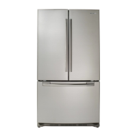
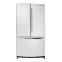
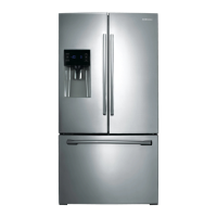
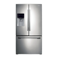
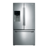
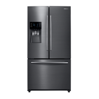
Details the characteristics and main functions of the refrigerator.
Lists electrical, operational, and refrigeration system specifications.
Shows a diagram of the refrigerator's interior components.
Provides a detailed specification chart for different models.
Displays dimensional drawings of the refrigerator.
Lists part names, codes, and quantities for optional materials.
Illustrates the path of refrigerant through the system.
Explains the basic principles of the refrigeration cycle.
Details the roles and operation of key refrigeration components.
Describes the different types of refrigeration cycles used.
Illustrates how air circulates within the refrigerator and freezer compartments.
Provides essential safety precautions before disassembly.
Details the steps for disassembling the refrigerator door.
Explains how to remove the refrigerator door handle.
Explains how to remove the freezer door handle.
Guides on how to disassemble and replace the refrigerator light.
Instructions for removing the display cover and dispenser assembly.
Steps for disassembling the water dispenser unit.
How to remove the glass shelf from the refrigerator.
Instructions for removing the foldable glass shelf.
Steps for removing the vegetable and fruit drawers.
Procedure for disassembling the case water filter.
How to remove the Cool Select Pantry component.
Steps for disassembling the motor damper.
Instructions for removing and installing the water filter.
How to remove the gallon door bin.
Steps for removing the vertical hinged section.
Procedure for removing the evaporator cover in the refrigerator section.
How to disassemble the evaporator in the refrigerator.
Steps for disassembling the freezer door.
Instructions for removing the ice maker.
How to disassemble the auger motor fan assembly.
Steps for removing the freezer light.
Procedure for removing the freezer door switch.
How to remove the evaporator cover in the freezer section.
Steps for disassembling the evaporator in the freezer.
Instructions for disassembling the machine compartment (motor fan).
Steps for disassembling and connecting the compressor.
How to disassemble the main and inverter PCBs.
Explains various diagnostic functions and test modes.
Details how to enter and use test modes for manual operation and defrost.
Describes error displays related to communication failures.
Explains how to perform and interpret self-diagnostics.
Shows how load conditions are displayed on the panel.
Explains how to set and use the exhibition mode.
Details how to access and change various setting options.
Provides tables for option settings, especially temperature adjustments.
Provides flowcharts for troubleshooting specific symptoms.
Troubleshooting steps when self-diagnosis indicates an error.
Diagnostic flowchart for when the cooling fan is not working.
Troubleshooting steps for a non-operating ice room fan.
Diagnostic guide for when the fresh food ice maker fails.
Troubleshooting steps for when the freezer ice maker fails.
Diagnostic flowcharts for defrost heater issues.
Troubleshooting steps when the unit has no power.
Diagnostic flowchart for compressor not running.
Troubleshooting for continuous alarm sounds.
Steps to troubleshoot a non-functioning panel PCB.
Troubleshooting guide for the pantry panel PCB.
Steps to diagnose why the refrigerator light is not working.
Troubleshooting for issues with ice water supply.
Diagnostic steps for when ice is not dispensed correctly.
Troubleshooting for the ice route motor.
Steps to troubleshoot issues with the IR sensor.
Explains LED blinking patterns and their associated protecting functions.
Shows the layout of components on the main PCB.
Illustrates the component layout on the inverter board.
Details connector locations on the main board.
Shows connector locations on the inverter board.
Wiring diagram for specific refrigerator models.
Provides a high-level block diagram of the refrigerator's system.
Shows a detailed block diagram of the inverter board system.
| Type | French Door |
|---|---|
| Ice Maker | Yes |
| Water Dispenser | Yes |
| Energy Star Certified | Yes |
| Height | 70 inches |
| Width | 35.75 inches |
| Cooling System | Twin Cooling Plus |
| Color | Stainless Steel |