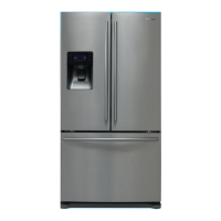
124
6-1) PCB Layout with part position
PCB DIAGRAM
1. DC12V,5V,GND supplied from SMPS PCB
2. Circuit for controlling Step-Valve (3-Way Valve) * Option
3. FAN MOTOR control part : To supply the power from 8.3V ~ 12V according to the motor types. (F,R,C,ICE)
4. EEPROM : Save and record every kinds of data.
5. Transmit inputted signals from every sensor into MICOM after eliminate the noise .
6. Micom : control the refrigerator Ceramic resonator : generate the basic frequency of Micom operation.
Reset IC : make Micom reset if input voltage of Micom is detected less than the specified voltage
7. PLC input/output
- PLC (Power Line communication) * Option(PLC module is not inserted unlessspecified occasion)
8. Operate ICE-MAKER, supply power to MOTOR, and sense the variation of switch.
9. Main Micom Panel Micom serial communication circuit
- Dispenser option input part (Water & Cover Ice route switch)
10. Pantry room display control part : display LED, detect KEY state.
11. Control Pantry room damper & Damper heater
12. Relay part for controlling the AC load : Relay control IC makes the relay ON/OFF by Micom signal.
13. Connector part : connect AC load
14. Diode option setting part
 Loading...