Do you have a question about the Samsung RS261MD Series and is the answer not in the manual?
Explains symbols for warnings and cautions, detailing their significance.
Defines various warning and safety symbols used within the manual.
Provides essential safety notices for appliance handling during installation, servicing, and repair.
Details important safety warnings and precautions to prevent injury and damage.
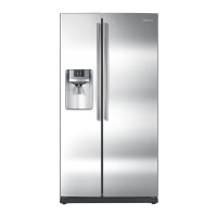
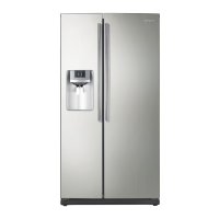
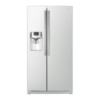
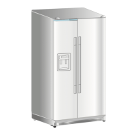
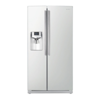
Introduces the main functions and key features of the refrigerator.
Details the key features and specifications of the refrigerator models.
Lists electrical, performance, and refrigeration system specifications for the models.
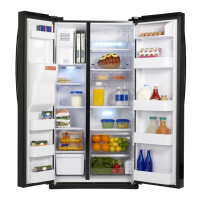
Illustrates and labels the internal components and compartments of the refrigerator.
Presents a comparative chart of model specifications, including capacity and dimensions.
Provides detailed dimensional drawings of the refrigerator in inches.
Lists specifications for optional materials used in the appliance.
Illustrates the path of the refrigerant through the refrigeration system.
Explains the airflow path for cooling within the refrigerator.
Provides crucial safety precautions and warnings before disassembling the appliance.
Step-by-step guide for disassembling the freezer door, including covers and hinges.
Instructions for disassembling the refrigerator door, covering upper and lower hinge removal.
Details the process for removing the control panel from the freezer door.
Explains how to remove the door gasket from the refrigerator liner.
Demonstrates the procedure for removing the door handle.
Illustrates how to remove the tempered glass shelves from the refrigerator.
Shows how to remove the plastic drawers from the refrigerator compartment.
Explains how to remove the gallon door bins from the refrigerator door.
Details the removal process for the water filter.
Step-by-step guide for removing the water filter tank from the refrigerator.
Instructions for disassembling the damper assembly in the refrigerator.
Illustrates how to remove the door bins from the freezer compartment.
Guides the disassembly of the ice maker compartment components.
Shows how to remove the plastic wire drawers from the freezer.
Demonstrates the removal of freezer shelves.
Explains how to remove the ice dispenser and ice maker assembly.
Details the steps to remove the ice maker kit.
Instructions for removing the evaporator cover in the freezer.
Guides the removal of the upper duct assembly.
Explains how to disassemble the evaporator located in the freezer.
Shows how to access and remove the ambient thermistor.
Details the disassembly of components within the machine compartment, including the motor fan.
Explains how to use and cancel the forced operation modes for the refrigerator.
Describes the various audible alerts and sounds the refrigerator produces.
Explains error messages related to communication between MICOMs.
Details the function and operation of the Cooling Off mode for US models.
Describes the Exhibition Mode for non-US models used in showrooms.
Guides on performing and interpreting the refrigerator's self-diagnostic tests.
Lists error codes, items, descriptions, and diagnostic steps for self-diagnosis.
Explains how to check the operation status of various components.
Describes how the refrigerator restores settings after a power interruption.
Explains how to enter and use the set point shift function for temperature adjustment.
Provides a table for adjusting freezer temperature values.
Offers a table for adjusting refrigerator temperature values.
Details how the ice maker controls water supply quantity via the flow sensor.
Explains the control of ice ejection standby time for the ice maker.
Describes how to shift the ice maker sensor temperature settings.
Explains how to set the minimum compressor RPM to reduce continuous operation.
Describes the option for displaying temperature at all times.
Details options for the dispenser and homebar heater.
Provides a flowchart for troubleshooting when the unit does not receive power.
Offers a troubleshooting flowchart for compressor non-operation.
Presents a flowchart for troubleshooting defrost issues.
Guides on troubleshooting when a sensor defect causes self-diagnosis errors.
Provides troubleshooting steps for continuous alarm or buzzer sounds.
Addresses troubleshooting when the buzzer fails to sound.
Troubleshooting guide for abnormal operation or lighting of the panel PBA.
Troubleshooting steps for when the cooling fan motor does not operate.
Troubleshooting guide for internal lamps that do not illuminate.
Troubleshooting for issues with ice crushing or cubing functions.
Troubleshooting guide for when the ice maker fails to operate.
Troubleshooting steps for when no ice water is supplied.
Troubleshooting guide for when no water is supplied to the dispenser.
Provides a flowchart for diagnosing issues based on temperature sensor readings.
Exploded view and parts list for the freezer compartment.
Exploded view and parts list for the refrigerator compartment.
Exploded view and parts list for the main cabinet structure.
Exploded view and parts list for the freezer door assembly.
Exploded view and parts list for the refrigerator door assembly.
Shows the layout of components on the main PCB.
Illustrates the arrangement of connectors on the main PCB.
Provides a high-level block diagram of the refrigerator's system architecture.
Details the electronic schematic diagram of the refrigerator's circuits.
Explains the model naming convention and provides a Q&A section.
Details the nomenclature used for identifying refrigerator models.
Lists common problems and their solutions, presented as questions and answers.
| Total Capacity | 25.5 cu. ft. |
|---|---|
| Refrigerator Capacity | 16.5 cu. ft. |
| Freezer Capacity | 9.0 cu. ft. |
| Cooling System | Twin Cooling Plus |
| Ice Maker | Yes |
| Water Dispenser | Yes |
| Energy Star Certified | Yes |
| Type | Side by Side |
| Color | Stainless Steel |
| Width | 35 3/4 inches |