22
3
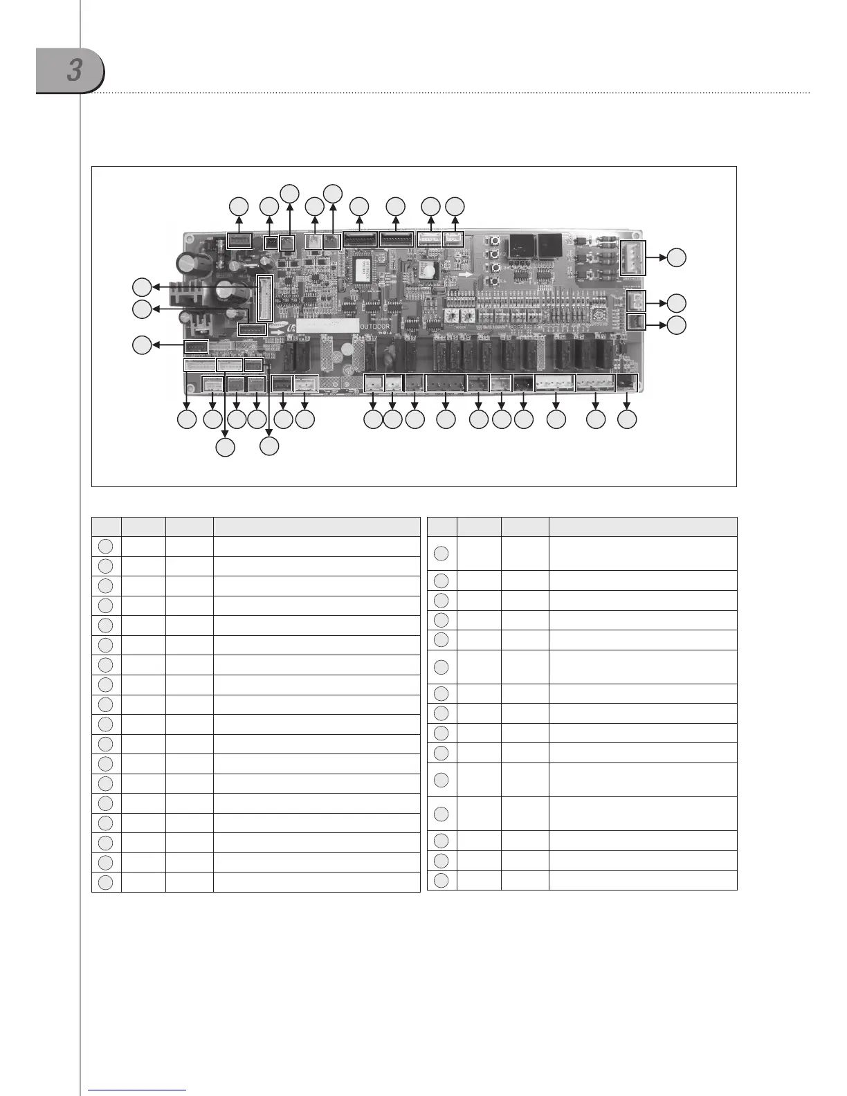
PCB connector layout
3-1. Main PCB
1 6 7 8 92
3
4
5
10
11
12
13232425262730
29
28
16202122 171819 1415
32
31
33
No. CN # COLOR FUNCTION
1 CN901 Red Power Trans Out (AC 17V)
2 CN13 Black 5V for Interface Module
3 CN31 Red Communication with Indoor Unit(COM1)
4 CN32 Yellow Communication with Outdoor Unit
5 CN12 Blue 12V for Interface Module
6 CN92 Black Sub Micom Download
7 CN91 Black Main Micom Download
8 CN10 White Main Micom Download (N/A)
9 CN100 White Main Micom Download (N/A)
10 CN83 Yellow 3 Phase Detection
11 OPT1 White Mode Selector (Cooling/Heating)
12 CN51 Red CT Sensor
13 CN70 Black AC 208~230V Input
14 CN76 Yellow Comp.1 CCH
15 CN15 White Comp.2 CCH
16 CN81 Black Oil Valve 1
17 CN82 Yellow Oil Valve 2
18 CN80 Red Liquid Bypass valve for FVI compressor
No. CN # COLOR FUNCTION
19 CN72 Blue
Magnetic contactor control
(Compressor)
20 CN74 Red Hot gas Bypass Valve
21 CN71 White PWM Valve
22 CN73 Yellow 4 Way Valve
23 CN75 White EVI Bypass Valve
24 CN86 Blue
Liquid Bypass valve for
DVI compressor
25 CN41 Blue Low Pressure Sensor
26 CN42 Red High Pressure Sensor
27 CN49 White Sump Sensor, Ambient Sensor
28 CN48 Red EVI-In Sensor, EVI-Out sensor
29 CN47 White
Oil Balance Sensor, Cond. Out
Sensor, Liquid Tube Sensor
30 CN44 White
Comp. Discharge 1,2 Sensor,
Suction Sensor
31 CN62 Blue Main EEV 1
32 CN64 Blue EVI EEV
33 CN69 White Main-BLDC Driver PCB Connector