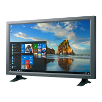
6. Remove 4 screws on the Rear Panel Bracket.
(15Ó : 6 screws)- Point;
7. Remove Bracket Panel from Front Cover.
8. Remove 1 screw on the Power PCB. (Point; )
9. Remove Function PCB from locking area of
Function Knob.
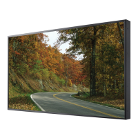
10. Remove 4 screws on the Front Bracket Panel.
11. Remove Front Bracket Panel.
12. Disconnect jack between Panel and Inverter
PCB.
13. Remove Rear Bracket Panel.
14. Remove 2 connecting screws between Rear
Bracket and Inverter PCB.
15. Remove Interface wire on the Rear side of
Panel.
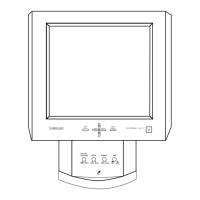
5-1-3 Stand Disassembly
1. Stand the stand assembly with the base close
to you.
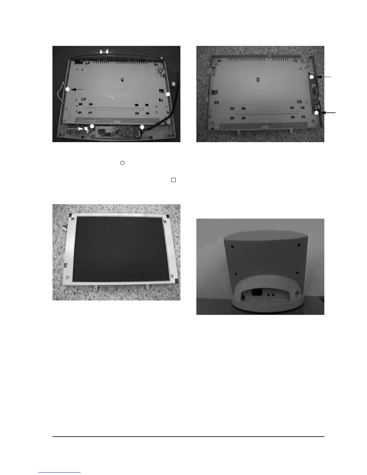
2. Remove the 4 screws on the back cover of the
stand and remove it.
3. Stand the stand assembly upside down.
5 Disassembly and Reassembly
5-2 SyncMaster 320TFT/520TFT
Figure 5-4
Figure 5-5
Figure 5-6
Figure 5-7