Do you have a question about the Samwon Tech Nova Series and is the answer not in the manual?
Guidelines for users to study and understand the manual for safe operation.
Instructions to protect the product and system from damage and ensure safe use.
Statements regarding warranties and liability for product use or defects.
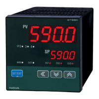
Sets the type of temperature sensor and its initial setting like TC, K1.
Defines the operation of output control for OUT 1, OUT 2, and OUT 3, including relay and analog types.
Parameters for control mode (AUTO/MAN), user screen display, and parameter locking functionality.
Parameters for setting running mode, SP types, SP values, and slope settings for ascending/descending.
Parameters for PID control, including deviation width, fuzzy function, and PID number selection.
Settings for auto-tuning process to measure characteristics and set PID parameters automatically.
Configuration for alarm types, set points, dead bands, and delay times for up to three alarms.
Settings for the type of retransmission output and its high/low limits for scaled output.
Parameters for communication protocol, speed, parity, data length, address, and response time.
Provides physical dimensions and panel cutout specifications for various ST series models.
Step-by-step instructions for mounting the controller into a panel, including cautions.
Details the specifications for the power cable, including wire gauge and voltage rating.
Specifies the type of terminals to be used for connections, such as M3.5 screw-compatible crimp-on terminals.
Shows the terminal layout and wiring diagrams for connecting external devices and signals.
| Brand | Samwon Tech |
|---|---|
| Model | Nova Series |
| Category | Controller |
| Language | English |