10 S&C Instruction Sheet 761-507
Installation
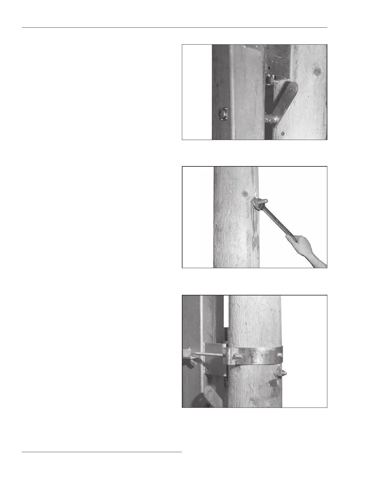
STEP 6. Guide the switch so the through-bolt heads enter
into the keyhole slot and open slotted hole in the
switch base. See Figure 8.
STEP 7. Slowly lower the switch until it just bears on the
through-bolts. Fully tighten the bolts. See Figure
9. Then remove the lifting slings.
STEP 8. Attach the pole bands to the switch base anchor
brackets using the J-bolts furnished. Use a
stiffening block under each nut. See Figure 10.
Use a ⅝-inch diameter lag bolt (not fur nished)
to secure each pole band to the utility pole.
Proceed to “Installing Pipe Couplings with
Piercing Set Screws” on page 13.
Figure 8. Guiding the switch.
Figure 9. Bolting the switch.
Figure 10. Attaching the pole bands.
 Loading...


