S&C Instruction Sheet 761-507 19
Installation
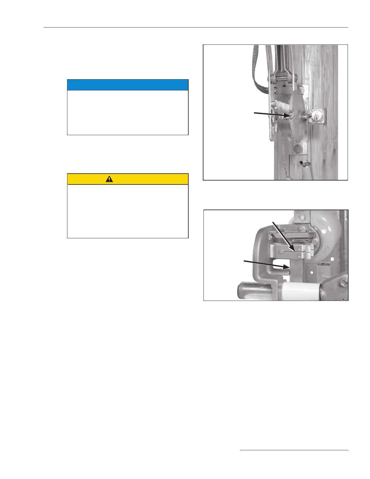
STEP 25. Block one of the two slots in the locking disc
with the blocking screw provided. (The slot to be
blocked depends on whether a locked-open or
locked-closed arrangement is required.) See
Figure 28.
NOTICE
Key interlocks are intended for proper
sequencing of switch operations; they are
not intended to provide security. The oper-
ating handle assembly includes a locking
bar for padlocking the switch in either the
open or closed position.
Checking Operation
STEP 26. Open and close the switch slowly through its
full travel.
CAUTION
The switch should be opened and closed
slowly only when checking for alignment
and complete closure.
When opening or closing the switch in ser-
vice, do not slow down or stop part way.
Arcing can occur if the switch is partially
open or partially closed.
Check to be sure that the following condi-
tions exist:
(a) With the operating handle as far as it will go in
the closing direction, both main contacts of each
switch pole are fully closed with the blade within
⅛-inch (3 mm) of the stop on the termi nal base
casting. See Figure 29.
Blocking screw
Figure 28. Blocking the slot in the interlock disc.
Figure 29. Check that the blade is fully closed and within
⅛-inch (3 mm) of the stop on the terminal base casting.
≤ ⅛-inch (3 mm)
Main contacts fully closed
 Loading...


