20 S&C Instruction Sheet 761-507
Installation
(b) With the operating handle as far as it will go in
the opening direction, the switch blades are 90
degrees from the Closed position. See Figure 30.
In the unlikely event that the above-described
conditions are not met, more switch blade travel
is required.
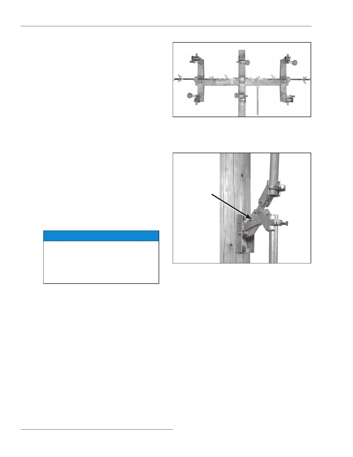
(c) Move the operating handle to its mid-posi tion to
take the strain off the operating-pipe linkage and
loosen the two bolts that clamp the driven arm of
the adjustable rod guide. See Figure 31.
(d) Lengthen the driven arm of the adjustable rod
guide one step ( -inch (9 mm)) and retighten
the bolts. Lengthening the driven arm increases
switch-blade travel. Then readjust for full
operating handle travel as described on page 18.
(e) Repeat this procedure—lengthening the driven
arm of the adjustable rod guide in one-step
increments and readjusting for full oper ating
handle travel—until full switch-blade travel is
attained.
(f) When satisfactory travel adjustment of the
operating handle and switch have been attained,
torque the bolts on the driven arm of the
adjustable rod guide, and the clamp bolt on the
rod guide (or switch drive lever) cou pling to nal
tightness. Then, tighten the asso ciated piercing
set screw, piercing the pipe, and continue turning
until a rm resistance is felt.
NOTICE
After readjusting, be sure to retighten the
clamp bolt and piercing set screw on the
pipe coupling at the rod guide (or switch
driver lever) immediately above the operat-
ing handle and the clamp bolts on the
driven arm of the adjustable rod guide.
Figure 31. Lengthening the driven arm of the adjustable rod guide.
Driven arm
Figure 30. Checking that the switch blades are 90 degrees from
the Closed position.
 Loading...


