14 S&C Instruction Sheet 761-507
Installation
Installing Vertical Operating Pipe
STEP 14. One of the pipe sections furnished is threaded at
one end to accommodate the operating handle
assembly. See Figure 17. Install this section of
pipe last, with the threads at the lower end.
If only one vertical operating-pipe section is
required, proceed to Step 17.
STEP 15. Mount the rod guide(s) with the arm pointing
upward as shown in Figure 18.
When an adjustable rod guide is included
mount it nearest the switch.
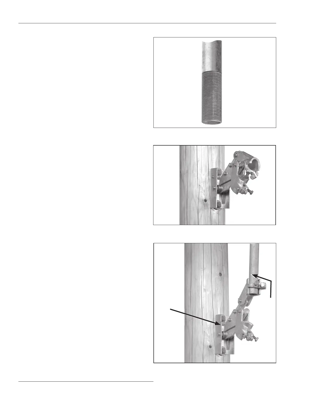
STEP 16. Install the upper section of vertical operating
pipe between the switch drive lever and the
upper most rod guide, with the rod-guide arm
point ing upward at a 45-degree angle. See
Figure19. (A positioning stud is furnished that
holds the rod guide at 45 degrees.) Follow the
directions in “Installing Pipe Cou plings with
Piercing Set Screws” on page 13.
Torque the clamp bolts to final tightness.
Then, tighten the piercing set screws, pierc-
ing the pipe, and continue turning until a firm
resistance is felt.
If more than one rod guide is used, install
vertical operating-pipe sections between the rod
guides in the same manner.
Figure 19. Installing the upper operating pipe section into the
rod guide.
Figure 18. Attaching the rod guide.
Positioning
stud
Upper-
most
section of
vertical
operating
pipe
Figure 17. Threaded vertical operating pipe.
 Loading...


