S&C Instruction Sheet 761-507 13
Installation
STEP 13. Attach the pole bands to the switch base anchor
brackets using the J-bolts furnished. Use a
stiffening block under each nut. See Figure 15.
Use a ⅝-inch diameter lag bolt (not fur nished)
to secure each pole band to the utility pole.
Installing Pipe Couplings with
Piercing Set Screws
WARNING
Failure to properly install pipe couplings with pierc-
ing set screws can cause slippage of operating pipe,
resulting in improper operation of the switch, arcing,
equipment damage, or electrical shock.
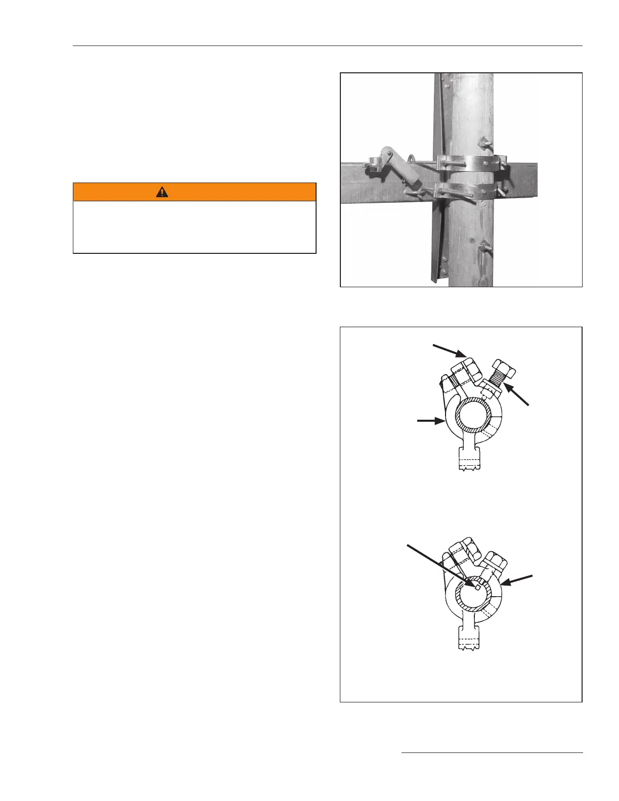
To properly install piercing set screws:
1. Make sure the cutting tip of the piercing set screw does
not protrude through the body of the clamp.
2. Insert the operating pipe section into the coupling and
nger-tighten the clamp bolt(s).
3. Adjust the operating pipe to the correct length. Then,
tighten the clamp bolt(s) to nal tightness.
4. Tighten the piercing set screw, piercing the pipe, and
continue turning until a rm resistance is felt.
5. Make sure the clamp bolt(s) are tight.
See Figure 16.
Figure 15. Attaching the pole bands.
Piercing set screw in shipping position (cutting tip
does not pro trude through body of the clamp)
Operating pipe installed, clamp bolt fully tightened,
and piercing set screw in final position
Clamp bolt
Clamp
Coupling body
Piercing
set screw
Slug pierced
from pipe
Figure 16. Installing the pipe couplings.
 Loading...


