16 S&C Instruction Sheet 761-507
Installation
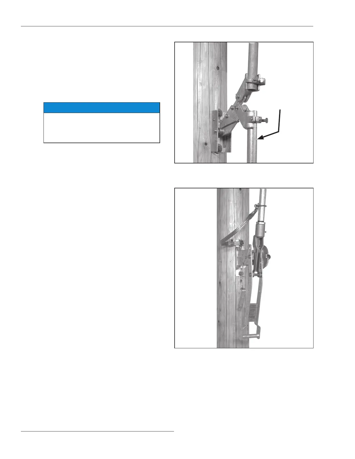
STEP 19. Insert the upper end of this pipe section in the
lowest rod guide or—if only one vertical oper-
ating-pipe section is used—the offset cou pling
attached to the switch lever. While holding the
operating handle at a point approximately
20 degrees from the Closed position, torque the
rod guide (or switch lever) coupling clamp bolt.
See Figure 22.
NOTICE
Do not tighten the piercing set screw at the
top of the lowest section of vertical operat-
ing-pipe until satisfactory operating handle
adjustment is attained.
STEP 20. Fasten the free end of the grounding strap to the
lowest vertical operating-pipe section a few
inches above the operating handle assem bly
with the U-bolt connector provided for this
purpose. See Figure 23. Then, connect the lower
end of the strap to a suitable earth ground, using
the grounding connector pro vided at that end of
the strap.
The grounding recommendations described in this document may
differ from the standard operating and safety procedures of cer tain
electric utility companies. Where a discrepancy exists, the operating
procedures of the electric utility apply.
Figure 22. Installing the lowest operating pipe section into the
rod guide.
Figure 23. Attaching the grounding strap.
Lowest section of
vertical operating pipe
 Loading...


