10 S&C Instruction Sheet 761-505
Installation
Attaching the Bell-Crank
STEP 3. Attach the bell-crank to its base or bracket (pole-
mounted arrangements only). See Figure 4.
If the bell-crank is mounted between switch
poles, the bell-crank will be connected to the
interphase pipe by a flat-bar or pipe type drag
link and an offset coupling. Attach one end of
the drag link to the driven arm of the bell-crank.
Attach the offset coupling to the other end of the
drag link.
Lifting the Switch
WARNING
DO NOT lift the switch poles by rigging on the live
parts. Avoid allowing the switch poles to swing while
lifting.
Lifting the switch by the live parts will damage the
switch. Rough handling may cause damage to the
blades and contacts.
Failure to lift the switch properly can result in switch
damage, causing improper operation, arcing, or
electrical shock.
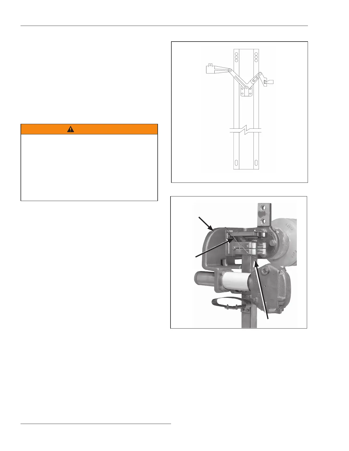
STEP 4. To minimize time-consuming nal adjust ments,
make sure each switch pole is fully closed and its
toggle mechanism is against the closed stop. Tie
the switch blades to their stationary main
contact assemblies and the toggle mechanisms
to their stops. See Figure5.
Figure 4. Attaching the bell-crank.
Figure 5. Tying the switch blade to the stationary main contact
assembly.
Blade
Stationary main
contact assembly
Tie
 Loading...


