22 S&C Instruction Sheet 765-510
STEP 17.
Upright mounting con guration shown;
inverted mounting con guration similar. For
installation on 34.5-kV Omni-Rupter Switches,
refer to the separate installation instructions
provided with the wildlife disks.
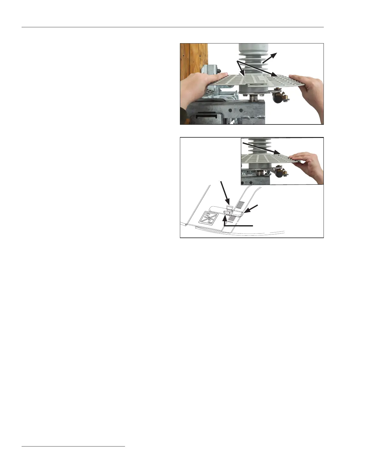
(a) To assemble the disks, t the disk around the
insulator on the blade end of the switch. See
Figure 21. Then, insert the locking tabs of
one-half of the disk into the open slot on the
other half to create a secure overlapping t.
Repeat the procedure on the opposite side of
the disk. When the halves are correctly
assembled, the S&C logo will be on top of the
disk on both sides. See Figure 22.
Snap tab into open slot
Upper locking tab
Lower locking tab
Slot
Figure 22. Snap the lower tab into the open slot.
Figure 21. Fit the disk halves around the insulator.
Insulator
Disk halves
Installation

 Loading...
