S&C Instruction Sheet 765-510 23
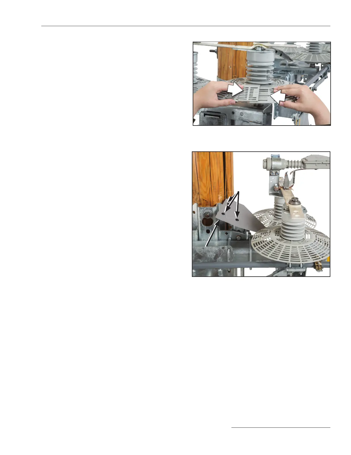
Figure 24. The pole-mounting bracket cover.
Mounting
bracket cover
Snap rivets
(b) Starting with the outside locking tabs rst,
squeeze the overlapping sides together until
the tabs audibly snap into place.
(c) Push the two halves of the disk together in
toward the insulator so the disk ts the
insulator as close as possible. See Figure 23.
Snap the upper locking tab rmly into place.
Both tabs should protrude through the open
slot, as shown in Figure 22 on page 22.
(d) Repeat Steps 17(a) through 17 (c) to install
the wildlife disks on the insulators on the
contact-end of the switch.
For Omni-Rupter Switches in the upright mounting
configuration:
(e) After installing the wildlife disks, install the
pole-mounting bracket cover with the snap-
rivets provided. See Figure 24.
Figure 23. Push the disk halves together. Snap the upper
tab into place. The disk halves should fit as tight against
the insulator as possible.
Push disk halves
together
Installation

 Loading...
