S&C Instruction Sheet 765-510 29
STEP 22.
Check the following on each phase.
(a) Open and close the switch and examine the
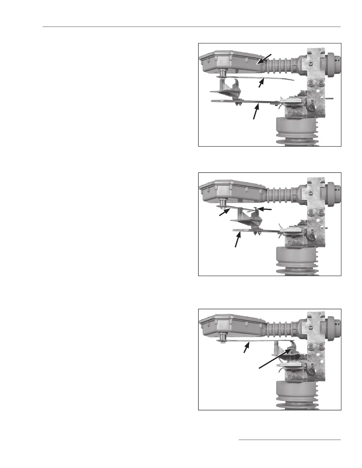
interrupter and blade alignment. The
interrupter and interrupter shunt arm must
be parallel to the sweep of the blade. See
Figure33.
(b) Slowly open the switch. The following
conditions should be met:
• As the blades move toward the Open posi-
tion, the operating cam shunt contact should
engage the interrupter shunt arm on the cop-
per-bronze contact surface of the shunt con-
tact. See Figure34.
• When the blade reaches its full travel the
interrupter shunt arm will be released and will
quickly snap back to its Closed position and
reset for the next operation. See Figure 33.
(c) Slowly close the switch. The following
conditions should be met:
• The interrupter shunt arm should be guided
into position by the curved back of the shunt
contact. See Figure 35.
Figure 33. Make sure the interrupter and interrupter shunt
arm is parallel to the sweep of the blade.
Interrupter
shunt arm (reset)
Blade
Interrupter
Figure 34. The shunt contact should engage the interrupter
shunt arm on the copper-bronze contact surface of the
shunt contact.
Interrupter
shunt arm
Blade
Shunt
contact
Figure 35. The shunt contact will guide the interrupter shunt
arm into position.
Interrupter
shunt arm
Shunt
contact
Installation

 Loading...
