S&C Source-Transfer PMH Pad-Mounted Gear With Micro-AT
®
Control
Outdoor Distribution (14.4 kv and 25 kv)
S&C ELECTRIC COMPANY
s
663-503
INSTRUCTION SHEET
Page 6 of 35
August 14, 1995
COMPONENTS
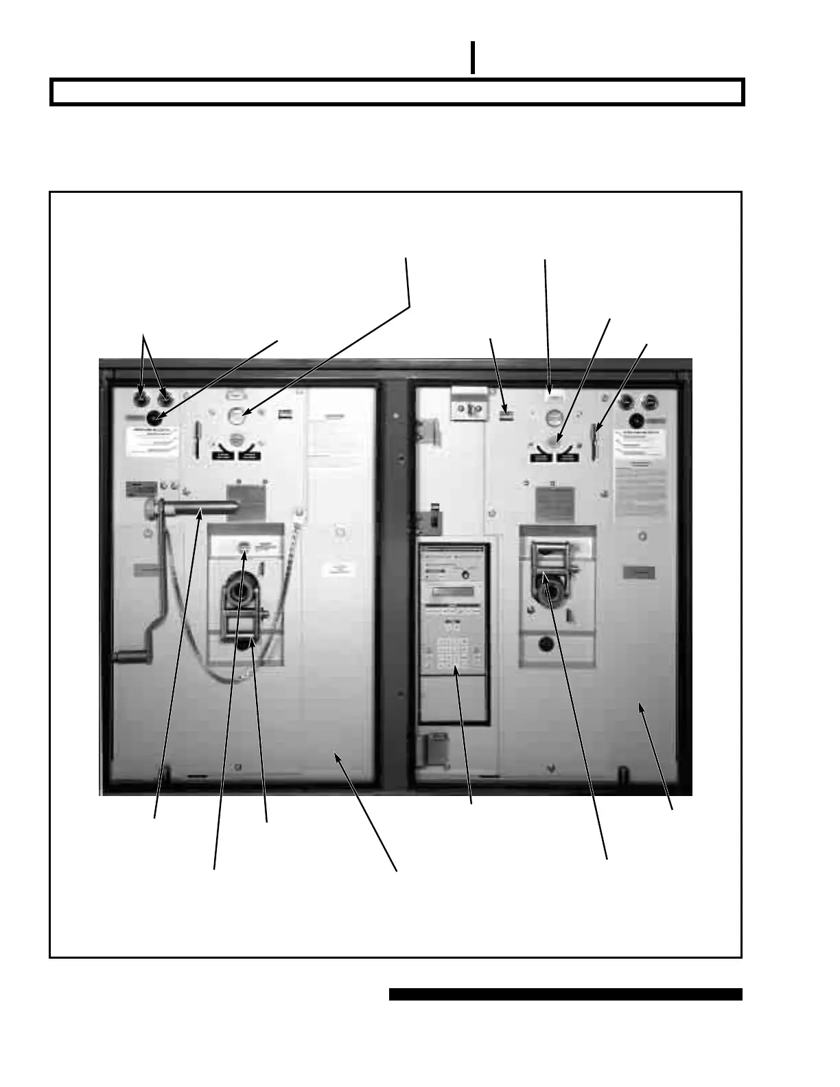
Figures 1 through 4 which follow illustrate many of the
basic components and features of S&C Source-Transfer
Pad-Mounted Gear. Before proceeding with the remainder
of the instructions, it is recommended that these figures
be reviewed to gain familiarity with the various compo-
nents and locations.
Figure 1. Low-voltage control compartment.
Bolted cover provides access to
input plug and shorting receptacle
for Micro-AT control
Operator target indicates whether stored-energy
operator is in switch-open or switch-closed
position and whether quick-make quick-break
mechanism is charged or discharged
Open/close
pushbuttons
Remote-control receptacle
(Catalog Number Suffix “-C11”)
Emergency-trip access cover
Operation
counter
Dual-purpose
manual handle
Operation
selector
Decoupler
handle
Charging shaft
Terminal-block
compartment
Switch-position
target
Micro-AT
Source-Transfer Control
Decoupler indicator