S&C Instruction Sheet 681-510 21
Operation
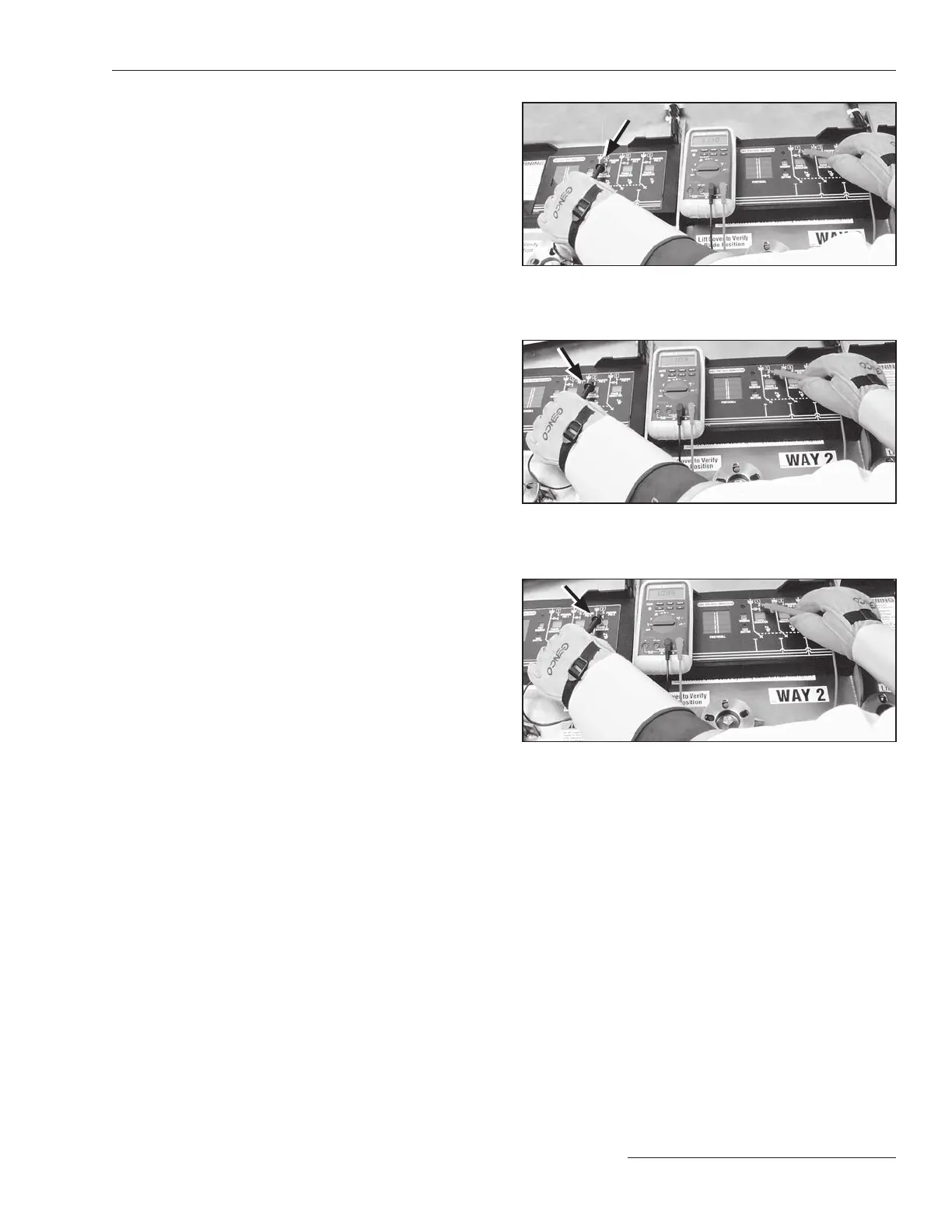
Figure 41. Measuring phase-to-phase voltage — Phase 1 to
Phase 1.
Figure 43. Measuring phase-to-phase voltage — Phase 3 to
Phase 1.
Figure 42. Measuring phase-to-phase voltage — Phase 2 to
Phase 1.
STEP 4. Determine the phase-to-phase relationships of
the two ways to be phased as follows:
(a) Remove the test probe of the voltmeter from
the switchgear tank.
(b) Place one of the test probes on Phasing Pin 1
of the rst way and place the other probe on
Phasing Pin 1 of the second way. Measure
the phase-to-phase volt age. See Figure 41.
When comparing the same phase of the two
ways, the voltage should be zero or close to
zero indicating that the cables are in phase.
(c) Keep the test probe on Phasing Pin 1 of the
second way and move the other test probe to
Phasing Pin 2 of the rst way. Measure the
phase-to-phase voltage. See Figure 42. When
comparing different phases of the two ways,
the voltage should be 1.7 to 2 times the
phase-to-ground voltage measured in Step 3
on page 20.
(d) Keep the test probe on Phasing Pin 1 of the
second way and move the other test probe
to Phasing Pin 3 of the rst way. Measure
the phase-to-phase voltage. See Figure 43.
Again when comparing different phases of
the two ways, the voltage should be 1.7
to 2 times the phase-to-ground volt age
measured in Step 3 on page 20.
(e) Repeat Steps 4(b) through 4(d) for Phasing
Pin 2 and Phasing Pin 3 of the second way.
(f) If all of the phase-to-phase relationships
are correct, the cables are in phase and are
properly installed.

 Loading...

