6 S&C Instruction Sheet 681-510
Components
Overview of Components
S&C Vista Underground Distribution Switchgear features
load-interrupter switches for switching 600-ampere main
feeders. The switchgear also features microprocessor-
controlled, resettable vacuum fault interrupters for
switching and protection of 600-ampere main feeders and
200-ampere taps, laterals, and subloops. These elbow-
connected components are enclosed in a sub mersible,
SF6-insulated, welded-steel tank. UnderCover™ Style (for
installation below grade), vault-mounted, and pad-mounted
switchgear styles are available. See Figures 1 through 3
and Figures 4 and 5 on page 7.
The three-position (CLOSED/OPEN/GROUNDED) load-
interrupter switches are manually oper ated and provide
three-pole live switching of 600-ampere three-phase
circuits. These switches also provide a visible gap when
open and internal grounding for all three phases.
The 200-ampere and 600-ampere fault interrupters
feature resettable vacuum interrupt ers in series with
manually operated three-position (CLOSED/OPEN/
GROUNDED) disconnects for isolation and internal
grounding of each phase. Fault interrupters provide
three-pole load switching and fault interruption through
25 kA symmetrical, or single-pole load switching and
fault interruption through 12.5 kA symmetrical (for other
possible ratings, refer to the nearest S&C Sales Office).
Fault interruption is initiated by a programmable over-
current control. For single-pole fault interrupters, the
overcurrent control can also be programmed to provide
three-pole fault interruption. See Instruction Sheet 681-530
for instructions on programming the control.
When the optional VOLTAGE indicator (option suffix
“-L1” or “-L2”) is specified, all routine operating tasks—
switching, voltage testing, and grounding—can be
accomplished by a single person without cable handling
or exposure to high voltage. Cable testing for faults can be
performed through the back of a user-supplied elbow with
insert or feedthru bushing insert, eliminating the need for
cable handling or parking stands.
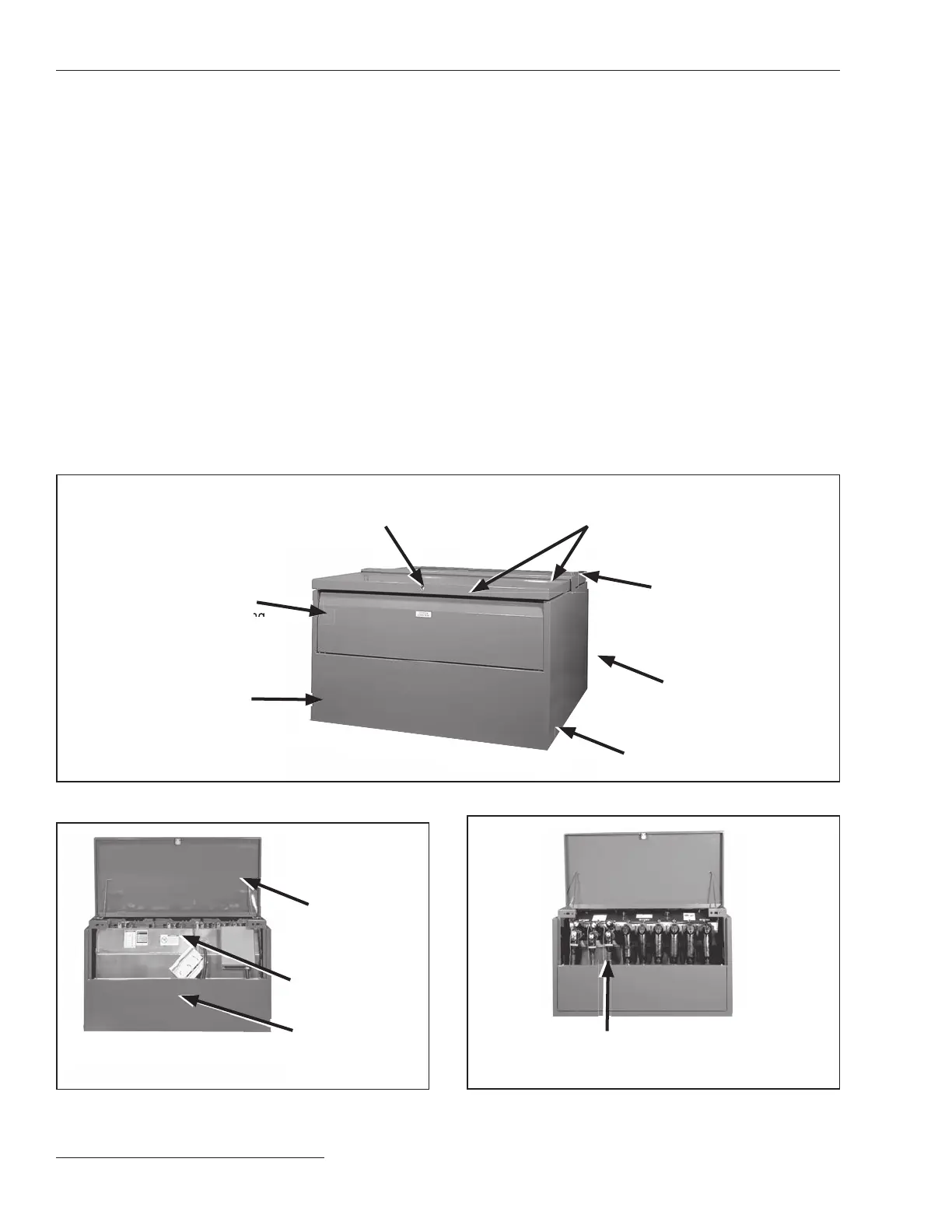
Operation
compartment
Holder
Switchgear
(panel removed)
Termination compartment (upper panel removed)
accommodates cables, elbows, surge arresters,
and feedthru inserts
Removable panel
for access to viewing
windows and operat-
ing mechanisms
Termination
compartment
Padlockable hinged roofs
for access to operation and
termination compartments
Operation compartment
S&C’s Ultradur® II
Outdoor Finish
Lifting bracket
Pentahead bolt
Figure 1. Pad-mounted enclosure (if furnished).
Figure 2. Operation compartment (panel removed).
Figure 3. Termination compartment (panel removed).

 Loading...

