S&C Instruction Sheet 681-510 7
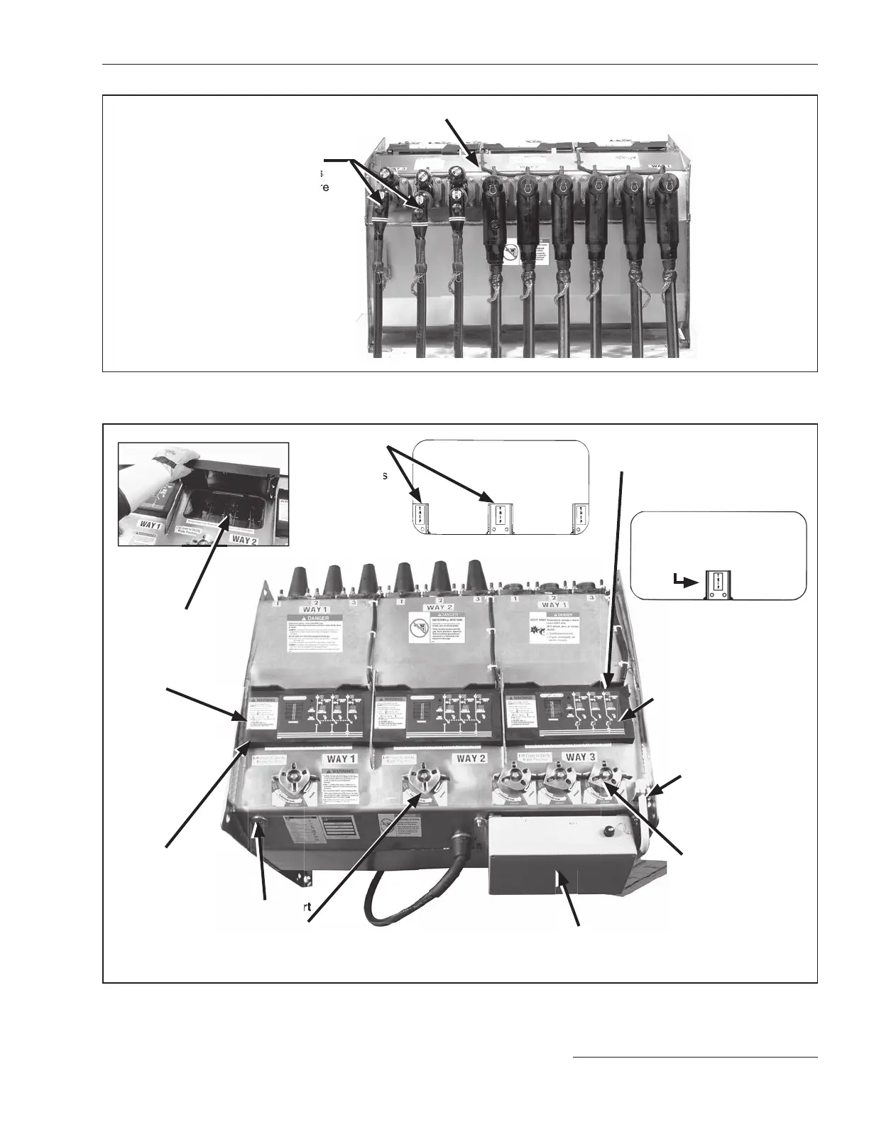
Components
Submersible tank
Fault-interrupter and load-
interrupter switch terminals
are equipped with 200-ampere
bushing wells or 600-ampere
bushings as specified
Optional VOLTAGE
indicator
with phasing (option suffix
“-L2”) includes liq uid-crystal
display indicating when volt-
age is present
Operating
mechanism
is padlockable in
any position
Viewing window
allows the operator
to see the blade
position, including
open gap if open
Manual operating
handle
Viewing window
under the VOLTAGE indicator
Trip indicators
for single-pole
fault interrupters
(can be seen
through the
viewing window)
TRIP indicator
for three-pole fault interrupters
(can be seen through the
viewing window)
Figure 4. Termination side of switchgear.
Figure 5. Top of switchgear.
interrupter switch terminals
are equipped with 200-ampere
SF
6
pressure gauge
is located inside the
tank and is visible
through the viewing
window
Gas-fill port
Operation selector
prevents inad vertent operation from the Closed
position directly to the Grounded position, and vice versa
S&C overcurrent control

 Loading...

