sa1dl5sm-rev0217
sandpi p erpump.com
Model SA1/SA25 • 6
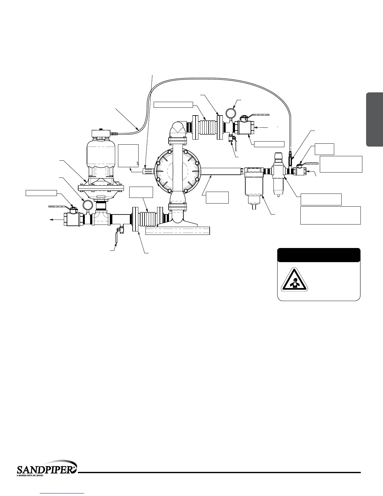
Principle of Pump Operation
Surge Suppressor
Shut-Off Valve
Pressure Gauge
Drain Port
Shut-Off
Valve
Check
Valve
Air Inlet
Discharge
Unregulated Air
Supply to Surge
Suppressor
Pipe Connection
(Style Optional)
Flexible Connector
Flexible
Connector
Vacuum
Gauge
Suction
Shut-Off Valve
Drain Port
Pipe Connection
(Style Optional)
Flexible
Connector
Air Dryer
Filter Regulator
P/N: 020.V107.000
Note: Pipe weight should not be supported
by pump connections.
In an emergency, the
shut-off valve at the air inlet
must be closed This stops
the operation of the pump.
Pmax: 125 psi = 8.6 bar
(Pmax: 100 psi = 7 bar
for non-metallic plastic pumps)
Muffler
(Optional
Piped
Exhaust)
In the event of a diaphragm rupture, pumped fluid can enter the air center section
of the pump and exit through the air exhaust port. When pumping hazardous fluids,
it is recommended to pump the exhaust air to a safe location.
Installation And Start-Up
Locate the pump as close to the product being pumped as possible. Keep the suction line length and number of ttings to a minimum. Do not reduce the suction line
diameter.
Air Supply
Connect the pump air inlet to an air supply with sufcient capacity and pressure to achieve desired performance. A pressure regulating valve should be installed to
insure air supply pressure does not exceed recommended limits.
Air Valve Lubrication
The air distribution system is designed to operate WITHOUT lubrication. This is the standard mode of operation. If lubrication is desired, install an air line lubricator
set to deliver one drop of SAE 10 non-detergent oil for every 20 SCFM (9.4 liters/sec.) of air the pump consumes. Consult the Performance Curve to determine air
consumption.
Air Line Moisture
Water in the compressed air supply may cause icing or freezing of the exhaust air, causing the pump to cycle erratically or stop operating. Water in the air supply can
be reduced by using a point-of-use air dryer.
Air Inlet And Priming
To start the pump, slightly open the air shut-off valve. After the pump primes, the air valve can be opened to increase air ow as desired. If opening the valve
increases cycling rate, but does not increase the rate of ow, cavitation has occurred. The valve should be closed slightly to obtain the most efcient air ow to pump
ow ratio.
Recommended Installation Guide
Available Accessories:
1. Surge Suppressor
2. Filter/Regulator
3. Air Dryer
1
2
3
Note: Surge Suppressor and
Piping must be supported after
the exible connection
CAUTION
The air exhaust should
be piped to an area
for safe disposition
of the product being
pumped, in the event of
a diaphragm failure.
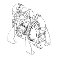
SUBMERGED ILLUSTRATION
UNIVERSAL ALL AODD, EXCEPT FLAP
2: INSTAL & OP