12
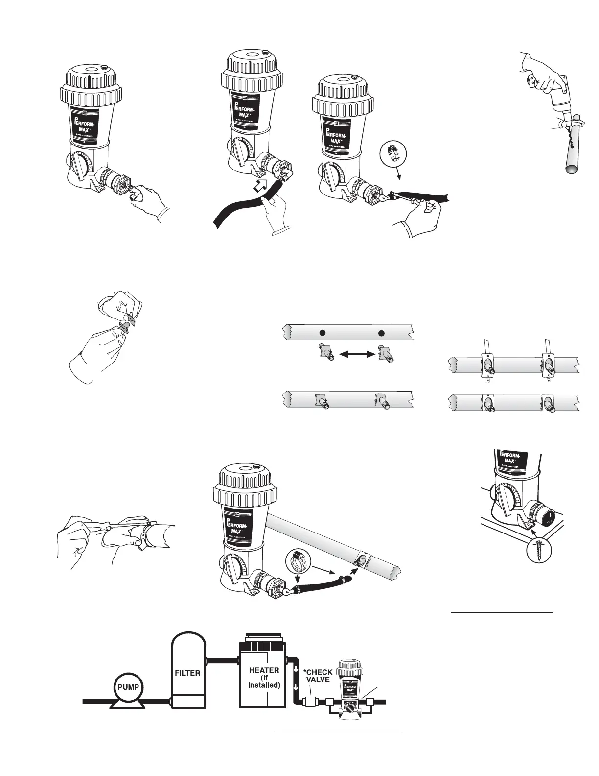
Screw elbow into reducer
bushings on both sides.
Cut tubing
to size
for each
Perform-
Max Feeder
connection
and attach
one to each
elbow with
clamps.
Tighten clamps
with a screwdriver.
When pipe is
totally dry, drill two
19/32” or 5/8”
holes, between
2” - 36” apart, on
the return line. Be
careful not to go
through other side
of pipe.
Attach a gasket to
each scoop.
Place scoops inside
holes so the inlet scoop
faces the water ow
and the outlet scoop
faces away from the
water ow. Scoop
arrows should be
facing each other when
correct.
2” – 36” apart on straight pipe
Arrows on scoops must face
each other.
Attach scoop clamps
over the scoops and
around the pipe.
Tighten scoop clamps
with a screwdriver.
Attach each hose to venturi
scoop male nipple with a
small clamp and tighten with
screwdriver.
6. 7. 8. 9.
10.
11. 12.
13.
14.
15.
16.
To prevent damage to heaters or lters, install a corrosion resistant check valve which
will reduce the back ow of chlorine gas when the feeder is turned off.
For better stability, Perform-
Max Feeder may be mounted
on a treated wood base using
Phillips pan head screws, one
in front and one in back. If you
have questions about stability,
please contact your dealer or
King Technology.
SCOOPS
2” – 36” APART
ON STRAIGHT PIPE