Do you have a question about the Sansui AU-217 and is the answer not in the manual?
| Frequency Response | 10Hz to 50kHz |
|---|---|
| Damping Factor | 30 |
| Input Sensitivity | 2.5mV (MM), 150mV (line) |
| Signal to Noise Ratio | 75dB (MM), 95dB (line) |
| Channel Separation | 50dB (MM), 55dB (line) |
| Output | 150mV (line) |
| Speaker Load Impedance | 8Ω to 16Ω |
| Weight | 6.7kg |
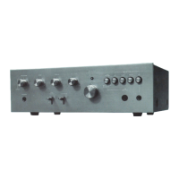
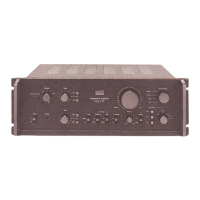
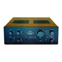
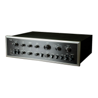
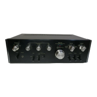
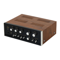
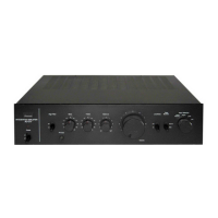
| Type | Integrated Amplifier |
Procedure for adjusting the bias current for L-CH and R-CH using a DC Volt Meter.
Location and parts list for the F-2757 Input Terminal Circuit Board.
Location and parts list for the F-2758 Equalizer Circuit Board.
Location and parts list for the F-2759 Tone Control Circuit Board.
Location and parts list for the F-2760 Power Amplifier Circuit Board.
Location and parts list for the F-2755 Output Connection Circuit Board.
Location and parts list for the F-2731 Voltage Selector Circuit Board.
Instructions on how to change the unit's power supply voltage settings.