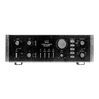
Do you have a question about the Sansui AU-D11 II and is the answer not in the manual?
| Damping Factor | 100 |
|---|---|
| Input Sensitivity (line) | 150 mV |
| Signal-to-Noise Ratio (line) | 100 dB |
| Input sensitivity (MC) | 0.25 mV |
| Input sensitivity (MM) | 2.5 mV |
| Signal to noise ratio (MC) | 74dB |
| Channel separation (line) | 70 dB |
| Input Sensitivity (DIN) | 150 mV |
| Channel separation (MM) | 70 dB |
| Speaker load impedance | 4Ω to 16Ω |
130 watts per channel into 8 ohms.
8 ohms
Less than 0.0028% at or below rated min. RMS power output.
(60 Hz: 7 kHz 4:1 SMPTE method) less than 0.0028% at rated power output.
DC to 300,000 Hz, +0 dB -3.0 dB.
+0.2 dB, -0.2 dB.
DISC-MC-HIGH 250 µV/40 ohms, DISC-MC-LOW 70 µV/3.2 ohms.
TAPE REC-1, 2 150 mV into 47 kilohms.
DISC-MC 80 dB, DISC-MM 90 dB, AUX, TUNER, TAPE PLAY-1, 2 110 dB.
Tone selector, BASS 10 dB at 50 Hz, TREBLE 10 dB at 10 kHz, SUBSONIC -3 dB at 16 Hz.
Power voltage 120/220/240V (50/60 Hz). Power consumption 470 watts 560 VA Rated.
466 mm (18-3/8") W 161 mm (6-3/8") H 431 mm (17") D.
17 kg (37.4 lbs) net 19 kg (41.8 lbs) packed.
Parts identified by the symbol on the schematic diagram and parts list are critical for safety.
The symbols UL, CSA, BS, UK, EU, AS, and XX on the parts list and schematic diagram have specific meanings.
Some printed circuit boards are not supplied assembled; stock numbers are not indicated for these.
Refer to the Common Parts List for omitted capacitors and resistors, issued February 1983.
Illustrates the power amplifier circuitry and its main components.
Illustrates the pre-amplifier circuitry and its main functional blocks.
Lists components and their locations on the Equalizer Amp circuit board.
Lists components and their locations on the Driver Amp circuit board.
Lists components and their locations on the Driver Amp circuit board.
Lists components and their locations on the Protector Circuit board.
Lists components and their locations on the Protector Circuit board.
Lists components and locations for the Input Selector circuit board.
Lists components and locations for the MM/MC Input Terminal board.
Lists components and locations for the Disk & Rec Selector circuit board.
Lists components and locations for the Volume Control circuit board.
Lists components and their locations on the Control Amplifier circuit board.
Lists components and locations for the Protector Circuit board.
Lists components and locations for the Input Indicator Lamp board.
Lists components and locations for the PHONES Jack board.
Detailed circuit diagram of the power amplifier section.
Detailed circuit diagram of the pre-amplifier section.
Lists components for the SPEAKERS Selector board.
Lists components for the Power Supply circuit board.
Lists components for the PROTECTOR LED board.
Lists components for the Power Supply circuit board.
Lists the items included in the product packaging for shipment.
Lists included accessories such as operating instructions and diagrams.