EasyManua.ls Logo

Sansui AU-X201 Service Manual

Sansui AU-X201
12 pages
To Next Page IconTo Next Page
Page #1 background imageLoading...
Page #1 background image
AU-X201/X301
SERVICE
MANUAL
SPECIFICATIONS
<AU-X20t>
Power
output
Min. RMS,
both channels driven^
from 20
to
20,000
Hz,
with
no
more than
0,05%
total harmonic
distortion.
30
watts
per channejdnto
1 kHz, 8
ohms.
Frequency
response {at
t
watt)
Overalbifrom
CD).
kto
100,000
Hz, +0
dB
â„¢3dB
Signal
to
noise ratio
{short-circuit,
A-network)
PHONO
{MM)
75 d8
CD,
TUNER,
LINE
105
dB
TAPE
PLAY-1,
2
;
105 dB
Power
consumption
150 watts
250
watts
Maxirnum
Weight
7.0
kg
(15.4
IbsL net
<AU.X301>
Power
output
Min.
RMS, both
channels
driven,
from
20
to 20,000
Hz, with
no more
than
0.05%
total
harmonic
distortion.
65 watts
per
channel
into 1
kHz,
8 ohms.
Frequency
response {at
1
watt)
Overall
(from CD)
1
to 150,000
Hz,
+0
dB
-3
dB
Signal
to noise
ratio
(short-circuit,
A-network)
PHONO
(MC)....
65
dB
PHONO
(MM)
80
dB
CD, TUNER,
LINE 105
dB
TAPE PLAY-k 2
105
dB
Power consumption
330
watts 410 VA
Rated
460
watts
Maximum
Weight
9.5
kg
(20.9
lbs) net
1
1 ,0
kg
(24.3
lbs)
packed
<
AU-X201/301
>
Load
impedance
4 to
16
ohms
Total
harmonic
distortion less
than 0.05% at
or
below rated min.
RMS
power
output
tntermodufation
distortion
(60
)Hz: 7 kHz
==4:1
5MPTE
method)
less than
0.05%
at
rated
power output
RIAA curve
deviation
(PHONO-MM,
20 Hz
to
20
kHz)
+0.5 dB,
^0.5
dB
Input
sensitivity and
impedance (at
1
kHz)
PHONO
(MC).... 420
^V/100
or 22
ohms
(AU-
X301
only)
PHONO
(MM)
3.5 mV/47
kohms
(Max.
input capability:
150
mV
at 1
kHz.fess
than
0.1%
total harmonic
distortion)
CD,
TUNER,
LINE
200 mV/47
kohms
TAPE
PLAY-1,
2
200
mV/47 kohms
Output
level
(at
1
kHz)
TAPE
REC-1,
2
200 mV Into
47
kohms
Controls
and
Filter
BASS...
iOdB at
50
Hz
TREBLE
db8 d8
at
10 kHz
SUBSONIC......
-3
dB at
16
Hz
(6
dB/oct)c
LOUDNESS
+8 dB at
50
Hz
(VOLUME:
--30
dB
position)::
+4
dB
at 10 kHz
Power
requirements
AC
120V/220V/240V,
50/60
Hz
For
U.S.A.
Sc Canada
..
AC
120V, 60
Hz
Dimensions..
448
mm
(17-11/16'")
W
136 mm
(5-3/80
H
311
mm
(12-1/4
"kD
INTEGRATED
AMPLIFIER
CAUTION
1. Parts
identified by the
A
symbol on
the
schematic
diagram
and the
parts
list
are critical
for
safety.
Use
only
replacement
parts
that have
critical
charac-
teristics
recommended
by the
manufacturer.
2.
Make
leakage-current
or resistance
measurements
to
determine that
exposed
parts
are
acceptably
in-
sulated
from
the
supply
circuit
before returning
the
appliance to
the
customer.
Design and
specifications
subject
to
chiinges
without
notice
for
im-
provements.
Due to
local
laws
and
regutatfons,
this
unit sold
In some areas
are not
equipped with
variable voltage
sdedtors.
Question and Answer IconNeed help?

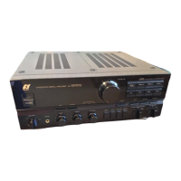
Do you have a question about the Sansui AU-X201 and is the answer not in the manual?

Sansui AU-X201 Specifications

General IconGeneral
BrandSansui
ModelAU-X201
CategoryAmplifier
LanguageEnglish

Summary

Specifications

AU-X201 Specifications

Power output, frequency response, S/N ratio, power consumption, and weight for the AU-X201 model.

AU-X301 Specifications

Power output, frequency response, S/N ratio, power consumption, and weight for the AU-X301 model.

General Specifications (AU-X201/301)

Load impedance, harmonic/intermodulation distortion, RIAA deviation, and input sensitivity for both models.

Cautionary Notes

Critical Safety Parts

Use only manufacturer-recommended replacement parts for safety-critical components.

Leakage Current and Resistance Checks

Perform insulation tests before returning the appliance to the customer.

Block Diagram

Electric Parts List

F-5716 Tone Control V.R. Board Parts

Lists components for the tone control potentiometer board.

F-5718 Protector Indicator Board Parts

Lists components for the protector indicator board.

F-5719 Phones Jack Board Parts

Lists components for the headphones jack board.

F-5720 Speakers Switch Board Parts

Lists components for the speaker switch board.

F-5721 Speakers Terminal Board (AU-X301) Parts

Lists components for the AU-X301 speaker terminal board.

F-5723 Speakers Terminal Board (AU-X201) Parts

Lists components for the AU-X201 speaker terminal board.

F-5717 Power Amplifier Board Parts

Lists components for the power amplifier board.

F-5722 Power Supply Board Parts

Lists components for the power supply board.

F-5751 EQ Amp. Input Terminal Board Parts

Lists components for the EQ amplifier input terminal board.

F-5735 Selector Switch Board Parts

Lists components for the selector switch board.

F-5752 Tape/DAT Terminal Board Parts

Lists components for the tape/DAT terminal board.

Parts Location on Circuit Boards

F-5717 Power Amp. Board Component Location

Shows component placement on the power amplifier board.

F-5721 Speakers Terminal Board (AU-X301) Component Location

Shows component placement on the AU-X301 speaker terminal board.

F-5735 Selector Switch Board Component Location

Shows component placement on the selector switch board.

F-5719 Phones Jack Board Component Location

Shows component placement on the headphones jack board.

F-5718 Protector Indicator Board Component Location

Shows component placement on the protector indicator board.

F-5751 EQ Amp. & Input Terminal Board Component Location

Shows component placement on the EQ amplifier input terminal board.

F-5716 Tone Control Volume Board Component Location

Shows component placement on the tone control volume board.

F-5752 Tape/DAT Terminal Board Component Location

Shows component placement on the tape/DAT terminal board.

F-5722 Power Supply Board Component Location

Shows component placement on the power supply board.

F-5720 Speakers Switch Board Component Location

Shows component placement on the speaker switch board.

F-5723 Speakers Terminal Board (AU-X201) Component Location

Shows component placement on the AU-X201 speaker terminal board.

Other Parts

Front View Parts List

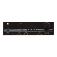
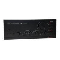
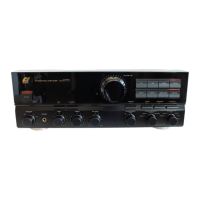
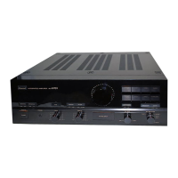
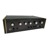
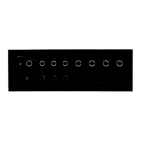
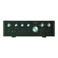
Lists external parts visible on the front of the unit.

Rear View Parts List

Lists external parts visible on the rear of the unit.

Adjustments

Schematic Diagrams

AU-X201 Main Section Schematic

Detailed schematic diagram for the AU-X201 main section.

AU-X301 Main Section Schematic

Detailed schematic diagram for the AU-X301 main section.

AU-X201 Power Supply (Primary-side) Section

Schematic for the primary-side power supply of the AU-X201 across different models.

AU-X301 Power Supply (Primary-side) Section

Schematic for the primary-side power supply of the AU-X301 across different models.

Packing List

Accessory List

Related product manuals