Do you have a question about the Sansui AU-X911DG and is the answer not in the manual?
Adjusts HOT/GND and HOT/COLD balance for the driver amp channel.
Adjusts HOT/COLD balance for the flat amplifier channel.
Adjusts bias current for HOT and COLD amplifier stages.
Component layout for tape, video, send terminals, and EQ amp board.
Component layout for input changeover switch board.
Component layout for tape, video, send terminals, and EQ amp board (EU/EG).
Component layout for the input indicator board.
Component layout for the normal amplifier indicator board.
Parts list for input terminal and E.R.S. rotary ass'y board.
Parts list for tape, video, send terminal, and EQ amp board.
Parts list for return input terminal board.
Parts list for the control amplifier board.
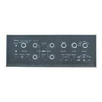
Identification of rear panel connections and components.
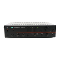
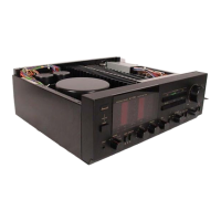
Component layout and identification on the top view.
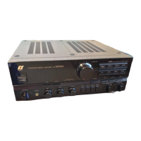
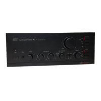
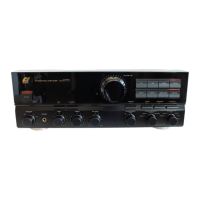
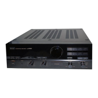
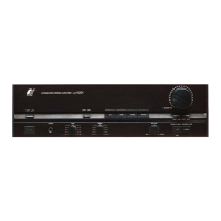
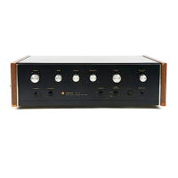
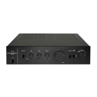
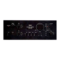
Identification of front panel controls, knobs, and switches.
Schematic for equalizer and control amplifier circuits.
Schematic for power amplifier and power supply circuits.
Schematic for the E.R.S. control section.
Schematic for the digital-to-analog converter circuits.
Schematic for the power supply circuits.
Instructions for replacing the F-6160 driver amplifier board.
Instructions for replacing the E.R.S. and F-6150 boards.
Instructions for removing and installing the front panel assembly.
Instructions for removing and installing the rear panel.
| Total Harmonic Distortion (THD) | 0.008% |
|---|---|
| Damping Factor | 100 |
| Channel Separation | 70 dB |
| Input Impedance | 47 kΩ |
| Speaker Load Impedance | 4 to 16 ohms |
| Signal-to-Noise Ratio | 110dB (line) |