Do you have a question about the Sansui AU-G55X and is the answer not in the manual?
Details the minimum RMS power output for both amplifier models.
Specifies the total harmonic and intermodulation distortion levels.
Lists frequency response range and RIAA curve deviation for phono inputs.
Provides input sensitivity and impedance for various audio sources.
Details the signal-to-noise ratio for different input types.
Lists characteristics of controls like Bass, Treble, Loudness, and Filters.
Outlines power voltage and consumption for AU-G55X and AU-G33X models.
Specifies the physical dimensions and net/packed weight of the units.
Emphasizes using manufacturer-recommended parts for safety-critical components.
Mandates checking for acceptable insulation and leakage current before customer return.
Explains the meaning of various international symbols (UL, CSA, etc.) used in the manual.
Provides information on separating and ordering parts for printed circuit boards.
Advises on referring to common parts lists for omitted capacitors and resistors.
Defines common abbreviations used throughout the service manual for components and terms.
Details the procedure for adjusting DC offset and bias current in the driver circuit.
Explains how to adjust the peak power indicator level for balance between channels.
Shows component layout and parts list for the F-4691 Control and Power Amplifier circuit board.
Shows component layout and parts list for the F-4702 Differential Amplifier circuit board.
Shows component layout and parts list for the F-4692 Protector circuit board.
Shows component layout and parts list for the F-4703 Driver Amp and Power Supply circuit board.
Shows component layout and parts list for the F-4700 Equalizer Amplifier circuit board.
Shows component layout and parts list for the F-4705 Front Lamp Indicator circuit board.
Shows component layout and parts list for the F-4704 Power Switch circuit board.
Shows layout and parts for Phono/Rec SW. & Input Terminal circuit board.
Shows layout and parts for Input Selector & Volume circuit board.
Shows layout and parts for Low/High Loudness SW. & Balance VR circuit board.
Shows component layout and parts list for the F-4690 Input Terminal circuit board.
Shows component layout and parts list for the F-4693 Speakers Terminal circuit board.
Shows component layout and parts list for the F-4694 Indicator circuit board.
Shows component layout and parts list for the F-4695 Phono Switch circuit board.
Shows component layout and parts list for the F-4696 MM/MC Indicator board.
Shows component layout and parts list for the F-4697 Protector Indicator board.
Shows component layout and parts list for the F-4698 Rotary Flex Board (REC Selector).
Shows component layout and parts list for the F-4701 Control circuit board.
Shows component layout and parts list for the F-4699 Pilot Lamp circuit board.
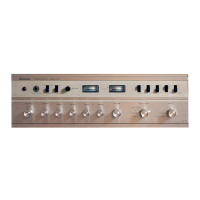
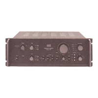
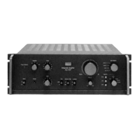
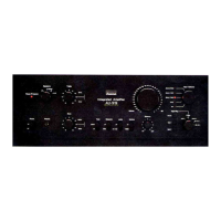
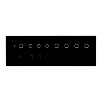
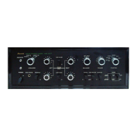
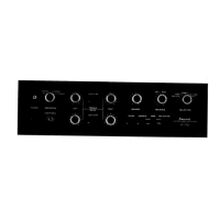
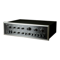
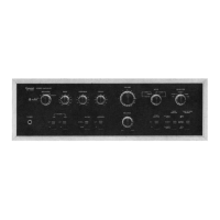
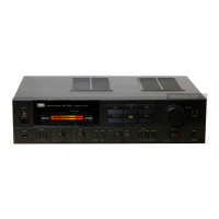
Identifies and lists external controls, knobs, and indicators visible on the front panel.
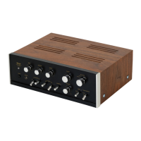
Identifies and lists internal components and their locations as seen from the top view.
Interior block diagram for the M5220L Audio Pre Amplifier integrated circuit.
Interior block diagram for the TA7317P Speaker Protector integrated circuit.
Interior block diagram for the HA12010 FL Display Tube Drive integrated circuit.
Interior block diagram for the TA7318P Meter Drive integrated circuit.
Interior block diagram for the M5220P Operational Amplifier integrated circuit.
Lists the items included in the product packaging, such as vinyl bags and carton cases.
Lists the accessories provided with the unit, like operating instructions.