EasyManua.ls Logo

Santec TSL-510 - User Manual

Default Icon
130 pages
Print Icon
To Next Page IconTo Next Page
Loading...
TUNABLE SEMICONDUCTOR LASER
Operation Manual
TSL-510

Table of Contents

Questions and Answers

  • A
    angelgrantAug 13, 2025
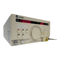
    Why Santec Measuring Instruments has no power?
    • D
      Daniel BerryAug 13, 2025
      The Santec Measuring Instruments might not be getting power because the cord is not properly connected. Ensure the cord is correctly connected. Another possible cause is a blown fuse or the absence of a fuse. In this case, open the fuse box lid and replace the fuse.
  • J
    Jenna HerringAug 17, 2025
    What to do if optical output power is too low on Santec Measuring Instruments?
    • C
      Christina MarshallAug 17, 2025
      If the optical output power is too low on your Santec Measuring Instruments, it might be due to an improper attenuator setting. Ensure that you set the attenuator properly. Another possible cause is a dirty connector surface. Clean the surface of the connector.
  • B
    Bobby ClarkAug 20, 2025
    How to fix GP-IB communication issues with Santec Measuring Instruments?
    • K
      Kelsey BatesAug 20, 2025
      If GP-IB communication is not possible with your Santec Measuring Instruments, it could be due to several reasons. First, the GP-IB address might not be set correctly; ensure you set the GPIB address correctly. Second, the delimiter setting might be incorrect; check the delimiter setting. Finally, the cable might not be connected properly; check the connection of the cable.
  • R
    Regina HansonAug 25, 2025
    What to do if Santec Measuring Instruments unit does not turn off?
    • A
      Amanda MaddoxAug 25, 2025
      If your Santec Measuring Instruments unit does not turn off, it may be due to some electrical faults. Keep pressing the Power ON/OFF key for at least 10 seconds.
  • V
    victoriawrightAug 28, 2025
    What to do if Santec Measuring Instruments has no light output?
    • A
      agonzalezAug 28, 2025
      If your Santec Measuring Instruments have no light output, there are several potential causes: * The LD drive key might not be turned on. Press the LD button to turn LD ON. * The target output power might not be set or is too low. Set the target output power. * The surface of the connector might be dirty. Clean the surface of the connector. * The interlock circuit might be open (Option). Short the interlock circuit. * The internal shutter might be closed. Open the shutter.
  • J
    Jason SchroederAug 31, 2025
    Why optical output power adjustment is not possible in Santec Measuring Instruments?
    • S
      Stephen AdamsSep 1, 2025
      If optical output power adjustment is not possible in your Santec Measuring Instruments, it could be because the power control is set to manual. Switch to Auto control. Alternatively, the power setting mode might not be selected; select the power setting mode.
  • D
    Drew RichardsonSep 4, 2025
    What to do if “TempErr” is displayed on the screen while LD is illuminated in Santec Measuring Instruments?
    • C
      Charles DavilaSep 4, 2025
      If “TempErr” is displayed on the screen while the LD is illuminated on your Santec Measuring Instruments, it could mean that the ambient temperature has exceeded the operating temperature range. Turn off LD output immediately. If the ambient temperature is not within the operating temperature range, turn LD output back on after the ambient temperature returns to within the operating temperature range.
  • J
    Jeremy RamirezSep 8, 2025
    What to do if “TempErr” is displayed while LD output is OFF in Santec Measuring Instruments?
    • J
      Jonathan JohnsSep 8, 2025
      If “TempErr” is displayed while LD output is OFF on your Santec Measuring Instruments, it means the LD output was automatically turned off because the LD temperature continued to rise due to abnormal LD temperature control, or the ambient temperature may have exceeded the operating temperature range. Set the ambient temperature to within the operating temperature range and then turn on LD output.

Summary

Introduction to the Operation Manual

How to Navigate the Manual

Explanation of Key Terms and Symbols

1. Safety Notes

2. Product Composition

3. Panel Descriptions

3-1 Front Panel Overview

Details the controls, display, and connectors on the front panel of the TSL-510.

3-2 Rear Panel Overview

Details the connectors and ports located on the rear panel of the TSL-510.

3-3 Bottom Panel Layout

Illustrates the bottom panel of the TSL-510, showing intakes and rubber legs.

3-4 Side Panel Layout

Illustrates the side panel of the TSL-510, showing intakes and rubber legs.

4. Installation Procedures

4-1 Operating Environment Guidelines

Specifies environmental conditions for safe and optimal operation of the TSL-510.

4-2 Power Supply Requirements

Details the power requirements, connection, and voltage for the TSL-510.

4-3 Interlock Functionality

Explains the function and connection of the external interlock circuit for safety.

5. Basic Operation Guide

5-1 Turning the Unit On

Step-by-step instructions for powering on the TSL-510 and initial setup.

5-2 Laser Diode (LD) Output Control

Details how to turn the laser diode (LD) output on and off safely.

5-3 Setting the Wavelength

Explains procedures for setting the desired output wavelength using the front panel.

5-4 Setting the Optical Power

Guides users on how to set the desired optical output power level.

5-5 Setting Wavelength Sweep Parameters

Describes how to configure parameters for wavelength sweep operations.

5-6 Executing Wavelength Sweeps

Provides instructions for initiating and managing wavelength sweep sequences.

5-7 Turning the Unit Off

Details the correct procedure for powering down the TSL-510 unit.

5-8 Understanding the Status Display

Explains the various status indicators and their meanings shown on the TSL-510 display.

6. Detailed Operation Features

6-1 Fine-tuning Wavelength

Explains how to precisely adjust the output wavelength with high resolution.

6-2 Coherence Control Function

Describes how to use the coherence control function to adjust spectral linewidth.

6-3 Switching Optical Power Control Modes

Explains how to switch between Auto and Manual modes for power control.

6-4 Setting Trigger Output Signals

Details how to configure trigger signal outputs for synchronization with external instruments.

6-5 External Modulation

Explains how to modulate the intensity of optical power using external signals.

6-6 Analog Signal Input

Describes how to use an external analog signal to fine-tune the wavelength.

6-7 Analog Signal Output

Explains how to output analog signals corresponding to wavelength or power.

6-8 Power Monitor Signal Output

Details the output of voltage signals based on the integrated power monitor.

6-9 Wavelength Memory Functions

Explains how to store and recall wavelength settings in memory.

6-10 Changing Wavelength Units

Describes how to change the display unit between wavelength (nm) and frequency (THz).

6-11 Changing Power Units

Explains how to change the display unit for power between mW and dBm.

6-12 Internal Shutter Operation

Details the operation of the internal shutter for temporarily interrupting optical power.

6-13 Changing the Password

Provides instructions on how to change the device's password for security.

6-14 Displaying Product Information

Explains how to view product details such as serial number and firmware version.

6-15 Setting Wavelength Offset

Guides users on how to calibrate the output wavelength by setting an offset.

7. Operation by Communication

7-1 GPIB Communication Setup

Details the connection and configuration for GPIB communication.

7-2 RS-232 C Communication Setup

Explains the connection and communication settings for RS-232C interface.

7-3 USB Communication Setup

Covers USB connection, system requirements, and driver installation.

7-4 Command Reference

Provides a comprehensive list and description of SCPI and Santec specific commands.

8. Operating Principles

9. Technical Specifications

10. Maintenance Procedures

10-1 Daily Maintenance

Details basic cleaning procedures for dusting the instrument safely.

10-2 Cleaning the Optical Connector

Explains the procedure for cleaning the optical connector to ensure proper output.

10-3 Replacing Fuses

Provides instructions for replacing the fuses in the TSL-510.

10-4 Inspection and Calibration

Recommends regular inspection and calibration for maintaining accuracy.

10-5 Long-Term Storage Guidelines

Gives guidelines for safely storing the instrument for extended periods.

11. Re-Packing and Shipping

11-1 Re-Packing Instructions

Details how to properly pack the instrument for shipment, using original or alternative materials.

11-2 Packing Procedures

Provides step-by-step instructions and diagrams for packing the TSL-510.

11-3 Shipping Advice

Offers advice on handling and labeling the package during shipping.

12. Troubleshooting Guide

Santec TSL-510 Specifications

General IconGeneral
Wavelength Resolution0.1 pm
Optical Output ConnectorFC/APC
Output Power Stability±0.01 dB
Linewidth100 kHz
InterfaceGPIB
Output Power≥ +10 dBm

Related product manuals