EasyManua.ls Logo

Santec TSL-550 - User Manual

Default Icon
130 pages
Print Icon
To Next Page IconTo Next Page
Loading...
Tunable Semiconductor Laser
Operation Manual
TSL-550

Table of Contents

Questions and Answers

  • J
    Jerry SantanaAug 14, 2025
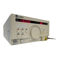
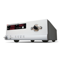
    How to fix Santec Measuring Instruments when there is no power?
    • P
      Patrick RileyAug 14, 2025
      If your Santec Measuring Instruments unit has no power, there are a couple of things to check: * First, make sure the power cord is properly connected. * Second, inspect the fuse. If there's no fuse or the fuse is blown, open the fuse box lid and replace it.
  • G
    Gordon PetersenAug 17, 2025
    What to do if Santec Measuring Instruments has no light output?
    • M
      Matthew RodriguezAug 17, 2025
      If there is no light output from your Santec Measuring Instruments, consider the following: * Ensure the LD drive key is turned on by pressing the LD button. * Verify that the target output power is appropriately set and not too low. * Check if the internal shutter is closed and, if so, open it. * Confirm that the interlock circuit is not open; short the interlock circuit if it is. * Ensure that the connector surface is clean.
  • B
    Benjamin ParsonsAug 20, 2025
    How to troubleshoot GP-IB communication issues with Santec Measuring Instruments?
    • C
      Charles ClarkAug 20, 2025
      If GP-IB communication is not possible with your Santec Measuring Instruments, check these items: 1. Verify that the GP-IB address is set correctly. 2. Check the delimiter setting to ensure it is correct. 3. Ensure the cable is properly connected.
  • A
    Adam MartinAug 25, 2025
    Why is the optical output power too low on my Santec Measuring Instruments?
    • D
      david74Aug 25, 2025
      If the optical output power of your Santec Measuring Instruments is too low, check the following: * Ensure the attenuator is set properly. * Verify the surface of the connector is clean.
  • J
    Joseph RogersAug 27, 2025
    What to do if optical output power adjustment is not possible with Santec Measuring Instruments?
    • H
      handersonAug 28, 2025
      If you cannot adjust the optical output power on your Santec Measuring Instruments, it might be due to the following reasons: * The power control may be set to manual; switch to Auto control. * The power setting mode may not be selected; select the power setting mode.
  • K
    Karen TateAug 31, 2025
    What does “TempErr” mean on Santec Measuring Instruments when LD is on?
    • T
      Tammy TaylorAug 31, 2025
      If “TempErr” is displayed on the screen of your Santec Measuring Instruments while the LD is illuminated, it could mean that the ambient temperature has exceeded the operating temperature range. Turn off LD output immediately. If the ambient temperature is not within the operating temperature range, turn LD output back on after the ambient temperature returns to within the operating temperature range. If “TempErr” continues to be displayed, please contact our office.
  • R
    Rodney RichmondSep 3, 2025
    What does “TempErr” mean on Santec Measuring Instruments when LD output is OFF?
    • M
      Megan JacksonSep 3, 2025
      If “TempErr” is displayed on your Santec Measuring Instruments while LD output is OFF, it indicates that the LD output was automatically turned off because the LD temperature continued to rise due to abnormal LD temperature control. The ambient temperature may have exceeded the operating temperature range. Set the ambient temperature to within the operating temperature range and then turn on LD output. If “TempErr” continues to be displayed, please contact our office.
  • M
    Mark DominguezSep 6, 2025
    What to do if Santec Measuring Instruments unit does not turn off?
    • J
      Julie ShieldsSep 6, 2025
      If your Santec Measuring Instruments unit does not turn off, it may be due to some electrical faults. Keep pressing the Power ON/OFF key for at least 10 seconds.
  • M
    Ms. Michelle Norman PhDSep 10, 2025
    What does “WL.Err” mean on Santec Measuring Instruments?
    • D
      darlene91Sep 10, 2025
      If the “W L . E r r ” status is displayed on your Santec Measuring Instruments, it indicates that the closed-loop wavelength control using the built-in wavelength monitor is not working properly. Please restart the product and turn on the LD. If "WL.Err" is still displayed, please contact us.

Summary

Introduction and Manual Guidance

Introduction

Provides a brief overview of the TSL-550 operation manual and its purpose.

How to Read the Manual

Explains the structure of the manual and recommends a reading order for optimal understanding.

Explanation of Terms

Defines key terms and symbols used throughout the operation manual.

Safety Notes

1-1 Intended Use

Defines the product's intended application and restrictions for safe operation.

1-2 Safety Markings

Explains the meaning of safety symbols used in the manual and on the product.

1-3 Operational Notes

Provides general guidelines and warnings regarding product modification and repair.

1-4 Laser Class

Details the laser classification and safety information according to IEC standards.

Product Composition

Panel Descriptions

3-1 Front Panel

Identifies and describes the controls and indicators on the front of the device.

3-2 Rear Panel

Identifies and describes the connectors and ports located on the rear of the device.

3-3 Bottom Panel

Illustrates the location of intakes and rubber legs on the bottom of the unit.

3-4 Side Panel

Illustrates the location of intakes and rubber legs on the side of the unit.

Installation

4-1 Operating Environments

Specifies the environmental conditions required for safe and optimal operation of the device.

4-2 Power Supply

Details the power requirements, cord connection, voltage compatibility, and fuse specifications.

4-3 Interlock

Explains the function and connection of the external interlock circuit for safety control.

Basic Operation

5-1 Turning on the Unit

Provides a step-by-step guide on how to power on the TSL-550 and its initial startup sequence.

5-2 LD Output

Details the procedure for turning on and off the Laser Diode (LD) output, including safety precautions.

5-3 Setting the Wavelength

Guides the user on how to input and set the desired output wavelength for the laser.

5-4 Setting the Optical Power

Explains how to set and adjust the optical output power level of the laser.

5-5 Setting the Wavelength Sweep

Details how to configure the parameters for performing wavelength sweeps.

5-6 Executing the Wavelength Sweep

Describes how to initiate and manage the wavelength sweep operations.

5-7 Turning off the Unit

Provides instructions for safely shutting down the TSL-550 unit.

5-8 Status Display

Explains the various status indicators and messages displayed on the device screen.

Detailed Operation

6-1 Fine-tuning

Describes how to perform fine adjustments to the laser's oscillation wavelength with high resolution.

6-2 Coherence Control

Explains how to use the coherence control function to manage spectral linewidth and power fluctuation.

6-3 Switching the Optical Power Control Mode

Details the process for switching between Auto and Manual modes for optical power control.

6-4 Setting the Trigger Output

Explains how to configure trigger signal outputs for synchronization with external instruments.

6-5 External Modulation

Covers the use of external signals to modulate the intensity of the optical power output.

6-6 Analog Signal Input

Describes how to use an external analog signal to fine-tune the laser's wavelength.

6-7 Power Monitor Signal Output

Explains how the device outputs a voltage signal corresponding to the integrated power monitor.

6-8 Wavelength Memory Function

Details how to store and recall wavelength settings for quick access.

6-8-2 Wavelength Registration

Guides on registering current wavelength settings into memory for later recall.

6-9 Changing the Unit of the Wavelength

Explains how to switch the display and input unit for wavelength between nm and THz.

6-10 Changing the Unit of the Power

Explains how to change the display and input unit for power between mW and dBm.

6-11 Internal Shutter

Describes the operation of the internal shutter for temporarily interrupting the optical power.

6-12 Displaying the Product Information

Guides on how to view essential product information such as serial number and firmware version.

Operation by Communication

7-1 GPIB

Details communication via the GPIB interface, including connection and functions.

7-1-2 GP-IB Function

Explains the various interface functions and subsets supported by the GP-IB communication protocol.

7-1-3. Setting the Address, Delimiter, and Command set

Guides on configuring GPIB settings like address, delimiter, and command set selection.

7-2 RS-232 C

Covers communication via the RS-232C serial interface, including connection and conditions.

7-3 USB

Details communication setup using the USB interface, including connection.

7-3-2. Communication Conditions and System Requirements

Lists the system requirements and communication conditions for USB connectivity.

7-3-3. Installing a USB Driver Software

Provides step-by-step instructions for installing the necessary USB driver software.

7-3-4. Installing a VCP Driver Software

Guides on installing the Virtual COM Port (VCP) driver for serial communication over USB.

7-4 Command Reference

Introduces the available command sets for controlling the instrument via communication interfaces.

7-4-1. Command set 1 (Complies with IEEE-488.2)

Lists and describes common commands compliant with IEEE-488.2 standards.

7-4-2. TSL-550 Specific Command set List (Command set 2)

Details the TSL-550 specific commands, compatible with existing Santec products.

Operating Principles

Specifications

9-1 Specifications

Lists the detailed technical specifications for the tunable semiconductor laser.

9-2 Regulations conformity

Outlines the various safety and EMC standards that the product complies with.

Maintenance

10-1 Daily Maintenance

Provides instructions for routine cleaning and care of the instrument.

10-2 Cleaning the Optical Connector

Explains the procedure for cleaning the optical connector to prevent output loss.

10-3 Replacing Fuses

Details how to replace the surge-resistant fuses located in the fuse box.

10-4 Inspection;Calibration

Recommends regular inspection and calibration services for maintaining accuracy.

10-5 Long-term Storage

Provides guidelines for safely storing the instrument for extended periods.

Re-packing and Shipping

11-1 Re-packing

Gives instructions on how to properly re-pack the instrument for shipment or repair.

11-2 Packing Instruction

Illustrates the correct method for packing the instrument and its accessories.

11-3 Shipping

Provides advice on handling and labeling the package during shipment.

Troubleshooting

Santec TSL-550 Specifications

General IconGeneral
Wavelength Resolution1 pm
Sweep Speed100 nm/s
InterfaceGPIB, Ethernet
Wavelength Range1500 - 1630 nm
Optical OutputSingle Mode Fiber (SMF)
Linewidth100 kHz (typ.)

Related product manuals