Do you have a question about the Santec PEM-340 and is the answer not in the manual?
Displays PER, optical power, and polarization angle simultaneously in real time.
Compensates for photodetector dark current for improved accuracy and dynamic range.
Supports GPIB and RS-232C for control and monitoring in automated systems.
Provides analogue output for monitoring measured parameters, useful for feedback loops.
Allows stopping the polarizer to measure optical power with faster response time.
Offers selectable measurement speeds (2.5Hz, 5Hz, 10Hz) for flexibility.
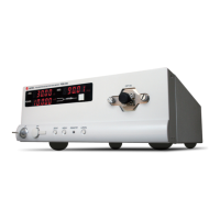
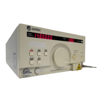
Details the displays and controls on the front of the PEM-340 unit.
Identifies connectors and features on the rear of the PEM-340 unit.
Guidelines for safe and trouble-free operation regarding environmental conditions.
Information on connecting the unit to a power source and voltage requirements.
Instructions for switching the PEM-340 unit on and off using the key switch.
Procedures for correctly connecting an optical fiber to the input connector.
Details on performing the offset cancel function for accurate measurements.
How to toggle the optical power display between mW and dBm.
Explains the PER averaging function and its availability via commands.
Instructions for configuring the GPIB address and delimiter settings.
How to change and store measurement speed and wavelength range.
Description of the analogue interface and pin assignments for output signals.
Procedure for changing the optical connector type (e.g., FC to SC).
Details on establishing and using GPIB communication with the device.
Information on connecting and controlling the device via RS-232C interface.
Lists and explains the control commands for device operation via interfaces.
Provides sample programs for GPIB and RS-232C communication.
General guidelines for handling, operation, and storage of the instrument.
Instructions for cleaning the unit and connectors to ensure performance.
Information on how to replace fuses in case of failure.
Recommendation for regular inspection and calibration for optimal performance.
Instructions for properly re-packing the instrument for shipment.
Guidelines for labeling and handling the package during shipping.
| PDL Resolution | 0.001 dB |
|---|---|
| Wavelength Accuracy | ±0.01 nm |
| Output Power Accuracy | ±0.5 dB |
| Output Power Resolution | 0.01 dB |
| Modulation Frequency Accuracy | ±0.1% |
| Modulation Frequency Resolution | 0.1 Hz |
| Modulation Depth Resolution | 0.1% |
| Polarization Extinction Ratio (PER) Measurement | 0-40 dB |
| Interfaces | USB |
| Modulation Depth Range | 0% to 100% |