Polarization Extinction Ratio Meter PEM-340
8-7
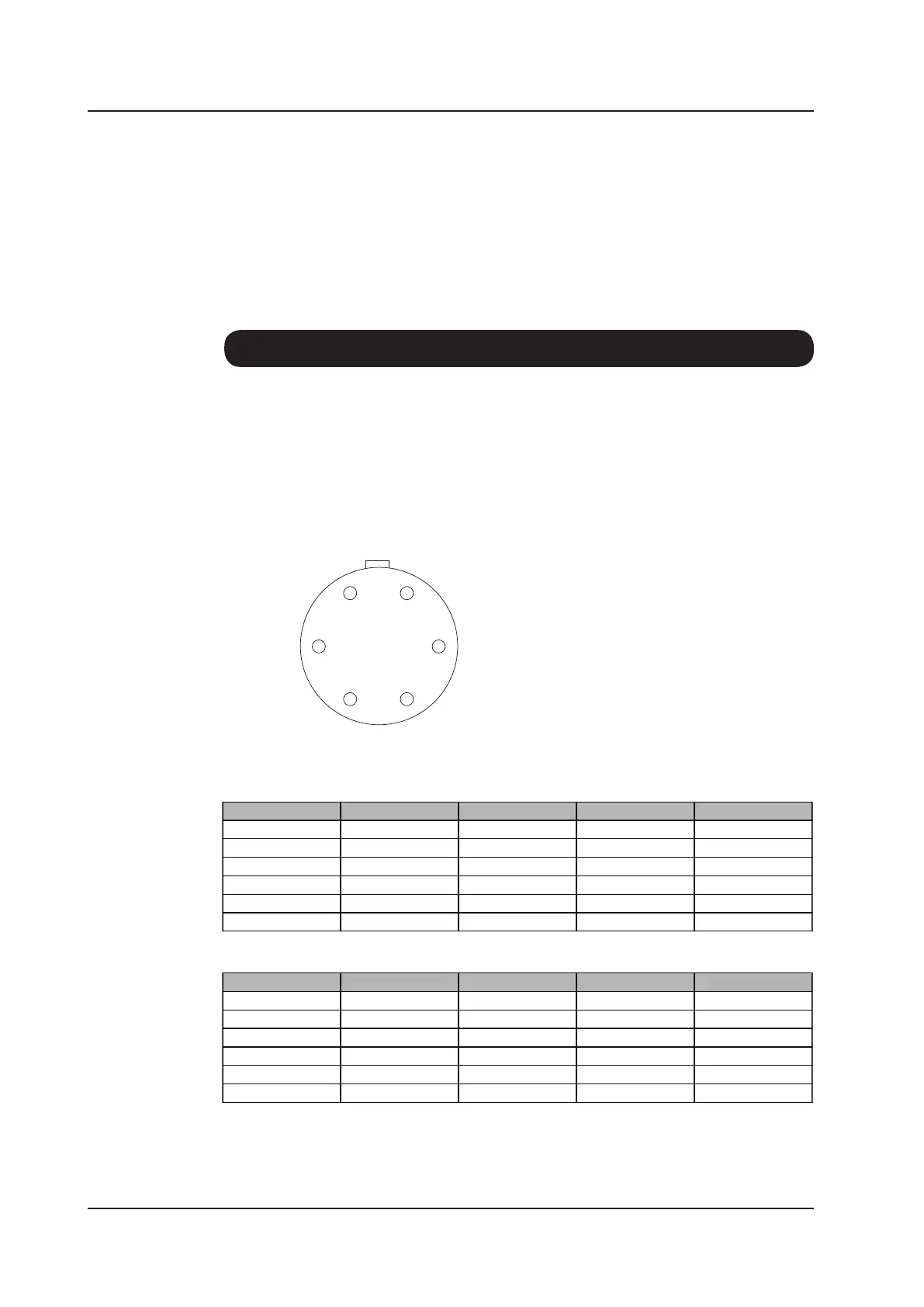
8-8. Analog Output
The analog interface (AIF) located on the rear panel of the PEM-340 enables the measured
signals to be monitored as analogue voltages. The voltages mirror directly the values displayed
on the front panel with the same refresh rate. The connector is a Hirose Electric HR10-7R-
6S. The corresponding plug is a Hirose Electric type HR10-7P-6P. The pin assignment for the
connector is detailed below.
Front view of the PEM-340 AIF connector
* The "analogue through" signal should be monitored when the polarizer is stopped.
Normal power Model
High-power Model
Pin No. Parameter Output Signal Measured Parameter Example
1 Optical Power 0 ~ 3 V -40 ~ +20 dBm 0 dBm = 2.0 V
2 GND - - -
3 PER 0 ~ 2 V 0 ~ 40 dB 20 dB = 1 V
4 GND - - -
5 Polarization Angle 0 ~ 1.8 V -90 ~ 90 deg 0 deg = 0.9 V
6 Analog Through* 0 ~ 2.5 V - -
Pin No. Parameter Output Signal Measured Parameter Example
1 Optical Power 0 ~ 3 V -50 ~ 10 dBm 0 dBm = 2.5 V
2 GND - - -
3 PER 0 ~ 3.5 V 0 ~ 70 dB 20 dB = 1 V
4 GND - - -
5 Polarization Angle 0 ~ 1.8 V -90 ~ 90 deg 0 deg = 0.9 V
6 Analog Through* 0 ~ 2.5 V - -