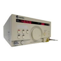
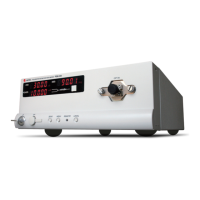
Tunable Semiconductor Laser TSL- 550
6-11
6-6 Analog Signal Input
A function used to ne-tune the wavelength according to the external input voltage.
Input the signal into the BNC connector labeled ”Analog Input” inside the cover at the
bottom of the front panel.
Specications
Input voltage range: –1.5 to +1.5 V
Rate of wavelength change: -40pm/V(Typical)
The high-frequency modulation terminal is connected directly to the LD through
matching resistors and capacitors. Be careful of the input level since it is not
particularly protected. Bias to the LD is fed from the LD drive circuit through a coil.
When using high-frequency modulation, keep the following steps in mind:
(1) Make sure that the power of this device and the signal source are shut
off, and then connect the cable for modulation signal input.
(2) Turn ON the power of the body and the signal source.
(3) Turn the LD key ON to feed current to the LD.
(4)Set the power control mode to manual (refer to “6-3 Switching
the optical power control mode”).
(5) After current is fed to the LD, input the external signal.
(6) Stop the external signal before interrupting the injection current to the LD.
Specications
Modulation bandwidth: 2 to 100 MHz
Input level: 5Vp-p
Modulation depth: >10% (Typ.)
Input impedance: 50 Ω
If high-frequency modulation is not used, make sure to connect the terminator to
the input terminal. Failure to do so may degrade the stability of the light intensity.
CAUTION


 To Next Page