6
inch dimensions are approximate
inches cm mm
3 7.5 75
4 10 100
7 ⅞ 20 200
11 ¾ 30 300
15 ¾ 40 400
W
H
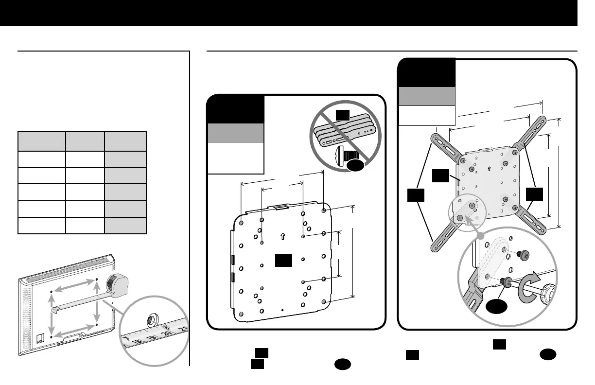
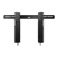
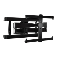
STEP 1 Attach Faceplate to TV
1.1 Measure Your TV Hole Pattern 1.2 Assemble Your Faceplate
Measure the width and height of your TV
hole pattern in mm.
Record your measurements:
Width_______mm x Height_______mm
Based on your TV hole pattern measurements
(W mm x H mm), determine your Faceplate
configuration: A, B, C, D or E.
A
200
[7 ⅞ in.]
200
[7 ⅞ in.]
400
[15¾ in.]
400
[15¾ in.]
B
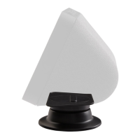
These smaller hole patterns only use
Faceplate
01
. Do not use the four TV
brackets
02
and eight screws
03
.
02
100
[4 in.]
100
[4 in.]
03
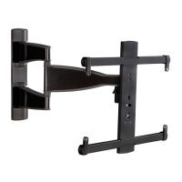
Assemble TV brackets
02
onto Faceplate
01
and secure using eight screws
03
in
the corner holes indicated.
02
01
01
03
300
[11 ¾ in.]
300
[11 ¾ in.]
02
100 x 100
200 x 100
200 x 200
For TV Hole Pattern
Measurements
(Dimensions in mm)
300 x 300
400 x 400
For TV Hole Pattern
Measurements
(Dimensions in mm)