CD MECHANISM REMOV~L
1)
1)
2)
3)
2)
1)
2)
3)
4)
5)
6)
7)
3)
(1)
1)
.. ,
2)
3)
4)
5)
6)
Preparations
Do not apply unnecessary force to the pickup when handling it.
Care should be taken not even to touch the lens or drive
circuit sections.
\
Do not apply unnecessary force (do not pull or push it forcefully) to remove the disc tray from its inside position.
Unnecessary force may break theteeth onthetray gear (CM6).
In the descriptions which follow, the numbers in the parentheses after the parts are reference numbers in the exploded views.
Refer to these views.
Removing and installing the disc tray
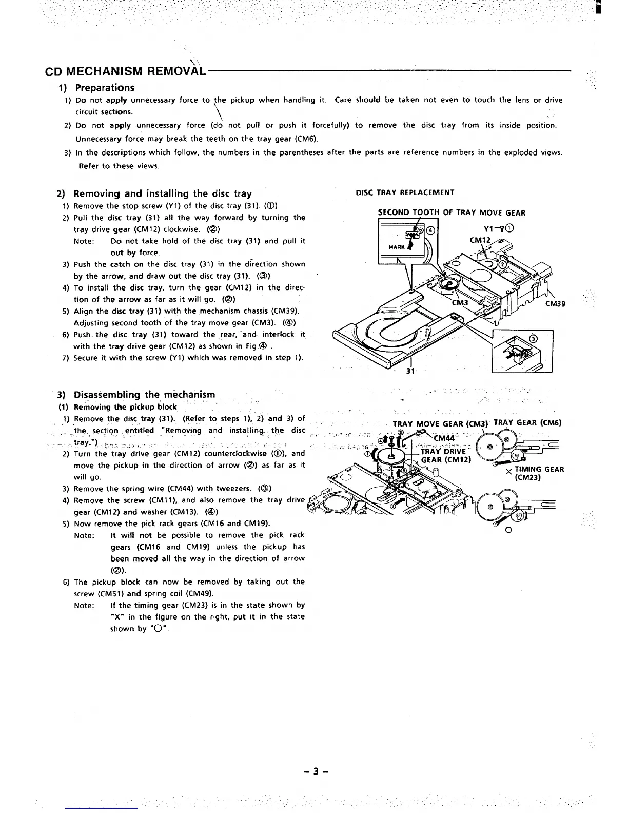
DISC TRAY REPLACEMENT
Remove the stop screw (Y 1) of the disc tray (31). (~)
Pull the disc tray (31) all the way forward by turning the
SECOND TOOTH OF TRAY MOVE GEAR
tray drive gear (CM12) clockwise. (@)
Note:
Do not take hold of the disc tray (31) and pull it
out by force.
Push the catch on the disc tray (31) in the direction shown
by the arrow, and draw out the disc tray (31). (@)
To install the disc tray, turn the gear (CM12) in the direc-
tion of the arrow as far as it will go. (@)
... ..
39 ‘“
Align the disc tray (31) with the mechanism chassis (CM39).
Adjusting second tooth of the tray move gear (CM3). (@)
Push the disc tray (31 ) toward the rear, ‘and interlock it
with the tray drive gear (CM12) as shown in Fig.@ .
Secure it with the screw (Y I ) which was removed in step 1).
,’, .-,. ., ..’ . . ..
Disassembling the mechanism ,.
, .-,
Removing the pickup block :” .-
..’ -,
.-
,,.
Remove, the disc tray (31). (Refer to steps 1), 2) and 3) of .- .
the. section , ent”itled”
“Removing and in~alling the disc
~ TRAY MOVE GEAR (CM3) TRAy GEAR (CM6)
... -..,. .. . .. . . . . . . . .
. .
tray-”), by, z~. !,,... r- , -,, -..,, ,- ,<
Turn the tray drive gear (CM12) ‘counterclockwise (~), and
move the pickup in the direction of arrow (@) as far as it
;-AR
will go.
Remove the spring wire (CM44) with tweezers. (@)
Remove the screw (CM1 1), and also remove the tray drive
gear (CM12) and washer (CM13). (@)
Now remove the pick rack gears (CM16 and CM19).
Note: R will not be possible to remove the pick rack
gears (CM16 and CM19) unless the pickup has
been moved all the way in the direction of arrow
(@).
The pickup block can now be removed by taking out the
screw (CM51) and spring coil (CM49).
Note: If the timing gear (CM23) is in the state shown by
“X- in the figure on the right, put it in the state
shown by
“O”.
-3-
\
“ (CM23)

 Loading...