.
MECHANISM REMOVAL (CD)
(2)
1)
2)
...
.,
,., ,
... ,..
3)
4)
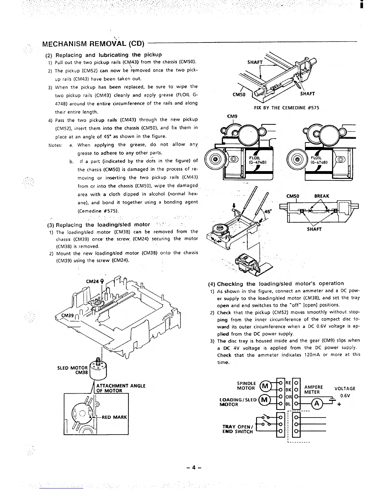
Replacing and lubricating the pickup
Pull out the two pickup rails (CN(143)from the chassis (CM50).
The pickup (CM52) can now be ‘&moved once the two pick-
up rails (CM43) have been taken out.
When the pickup has been replaced, be sure to wipe the
two pickup rails (CM43) cleanly and apply grease (FLOIL G-
474B) around the entire circumference of the rails and along
their entire length.
Pass the two pickup rails (CM43) through the new pickup
(CM52), insert them into the chassis (CM50), and fix them in
place at an angle of 45° as shown in the figure.
Notes:
a. When applying the grease, do not allow any
grease to adhere to any other parts.
b. If a part (indicated by the do;s in the figure) of
the chassis (CM50) is damaged in the process of re-
moving or inserting the two pickup rails (CM43)
from or into the chassis (CM50), wipe the damaged
area with a cloth dipped in alcohol (normal hex-
ane), and bond it together using a bonding agent
(Cemedine #575).
!,
\,.
(3)
Replacing the loading/sled motor ‘ ~‘‘ . -
1)
The loading/sled motor (CM38) can be removed from the
chassis (cM39) once- the screw.
(CM.24) securing the motor
(CM38) is removed.
2) Mount the new loading/sled motor (CM38) onto the chassis
(CM39) using the screw (CM24).
ATTACHMENT ANGLE
OF MOTOR
c
FIX BY THE CEMEDINE #575
CM9
..-
5
00
0
0
0
@
FLOIL
(G-47LB)
0
(4) Checking
the Ioadingk
1)
2)
3)
CM50
BREAK
SHkFT
;Ied motor’s operation
As shown in the figure, connect an ammeter and a DC pow-
er supply to the loading/sled motor (CM38), and set the tray
open and end switches to the “’off” [open] positions.
Check that the pickup (CM52) moves smoothly without stop-
ping from the inner circumference of the compact disc to-
ward its outer circumference when a DC 0.6V voltage is ap-
plied from the DC power supply.
The disc tray is housed inside and the gear (CM9) slips when
a DC 4V voltage is applied from the DC power supply.
Check that the ammeter indicates 120mA or more at this
time.
——
.:gal:

 Loading...