\.
MECHANISM REMOVAL (CD)
4)
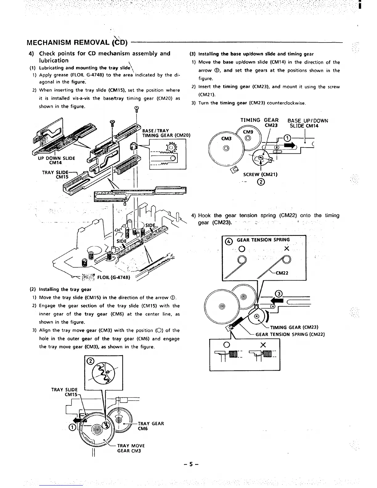
(1)
1)
2)
Check points for CD mechanism assembly and
(3)
lubrication
\
1)
Lubricating and mounting the tray slide ~
Apply grease (FLOIL G-474B) to the area indicated by the di-
agonal in the figure;
2)
When inserting the tray slide (CM15), set the position where
it is installed vis-a-vis the base/tray timing gear (CM20) as
3)
shown
in the figure.
y
(2)
1)
2)
3)
Installing the tray gear
Move the tray slide (CM15) in the direction of the arrow ~.
Engage the gear section of the tray slide (CM15) with the
inner gear of the tray gear (CM6) at the center line, as
shown in the figure.
Align the tray move gear (CM3) with the position (0) of the
hole in the outer gear of the tray gear (CM6) and engage
the tray move gear (CM3), as shown in the figure.
El
@
TRAY SLIDE L -
GEAR
Installing the base up/down slide and timing gear
Move the base upldown slide (CM14) in the direction of the
arrow 0, and set the gears at the positions shown in the
figure.
Insert the timing gear (CM23), and mount it using the screw
(CM21).
Turn the timing gear (CM23) counterclockwise.
TIMING
GEAR
BASE UP/
DOWN
*~~JJ14
ql+i- 1
,/’
@$ i
SCREW (CM21)
““- @
Hook the gear tension spring (CM22) onto the timing
gear (CM23). ~~ .: ‘
J
@ GEAR TENSlON SPRING
-.0 x“ ~
1’
.,,,,
..
3)

 Loading...