CD CHANGER OPERATION AND DESCRIPTION
4. When the TRAY closes and it reaches the tip of RIB part of LEFT TRAY GUIDE, the LOCK LEVER is lowered to release the
TRAY, and loading proceeds.
TRAY GuIDE HOLDER
LOCK \EVER
OPEN ~ CLOSE
TRAY ~OCK
RiB
/
TRAY RELEASE
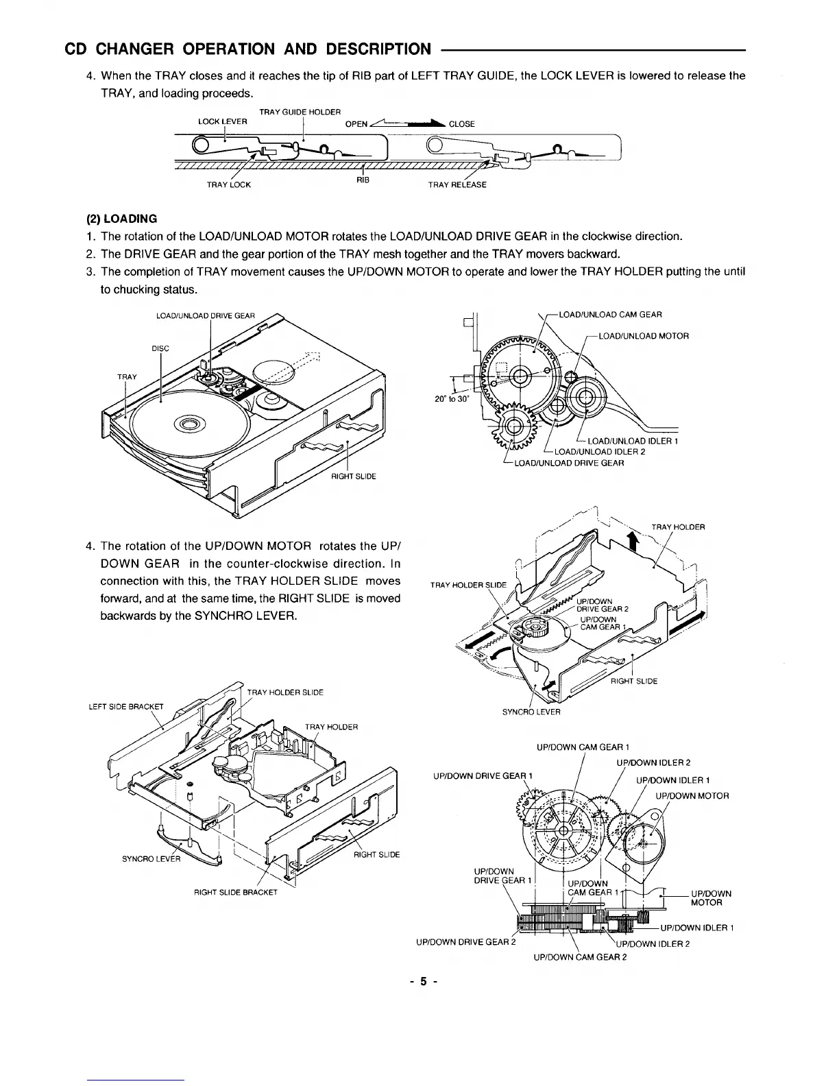
(2) LOADING
1. The rotation of the LOAD/UNLOAD MOTOR rotates the LOAD/UNLOAD DRIVE GEAR in the clockwise direction.
2. The DRIVE GEAR and the gear portion of the TRAY mesh together and the TRAY movers backward.
3. The completion of TRAY movement causes the UP/DOWN MOTOR to operate and lower the TRAY HOLDER putting the until
to chucking status.
4. The rotation of the UP/DOWN MOTOR rotates the UP/
DOWN GEAR in the counter-clockwise direction. In
connection with this, the TRAY HOLDER SLIDE moves
forward, and at the same time, the RIGHT SLIDE is moved
backwards by the SYNCHRO LEVER.
LEFT
~1-
\
LOAD/UNLOAD CAM GEAR
K r
LOAD/UNLOADMOTOR
L-LoAD/UNLOAD DRIVE GEAR
TRAY
SYNCRO LEVER
UP/DOWN CAM GEAR 1
//
UP/OOWN IDLER 2
UPIDOWN DRIVE GEA~l
UPIDOWN IDLER 1
RIGHT SLIDE BRACKET ‘
UP/DOWNDRIVEGEAR2
“\
‘UPIDOWN IOLER2
UPIDOWNCAMGEAR2
-5-
 Loading...


