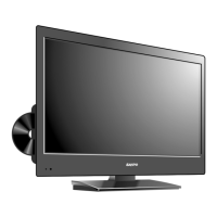
1. REMOVAL OF MECHANICAL PARTS
1-3: DVD MT PCB/LOADER UNIT (Refer to Fig. 1-3)
AND P.C. BOARDS
Remove the Shield Deck in the direction of arrow (A).
Be careful not to remove the LVDS cable forcibly, because
Remove the DVD MT PCB in the direction of arrow (B).
the LVDS cable may be damaged.
Disconnect the following connectors:
(CP2301, CP2302, CP2303, CP8501 and CP8502).
Remove the Loader Unit in the direction of arrow (C).
1-1: STAND ASS'Y (Refer to Fig. 1-1)
Remove the Stand Ass'y in the direction of arrow.
(1)
(1)
(1)
(1)
(B)
(A)
(2)
(1)
Stand Ass'y
(1)
Shield Deck
DVD MT PCB
(C)
Loader Unit
Short circuit using
a soldering iron.
1-2: BACK CABI ASS'Y (Refer to Fig. 1-2)
Remove the Back Cabi Ass'y in the direction of arrow.
Before your operation, please read "PREPARATION
Use the Lead Free solder.
Manual soldering conditions
• Soldering temperature: 320 ± 20
• Soldering time: Within 3 seconds
• Soldering combination: Sn-3.0Ag-0.5Cu
When Soldering/Removing of solder, use the drawing
equipment over the Pick Up Unit to keep the Flux
When installing the DVD Deck, remove all the soldering
on the short circuit position after the connection of Pick Up
PCB and DVD MT PCB connector.
Fig. 1-3
Fig. 1-1
Fig. 1-2
(1)
(2)
(2)
(2)
(2)
(2)
(2)
(2)
(2)
(2)
(2)
(2)
Front Cabi Ass'y

 Loading...